RZ/A2M SUB Board RTK79210XXB00000BE 2. Function specifications
R20UT4398EJ0100 Rev.1.00 2-6
2018.10.11
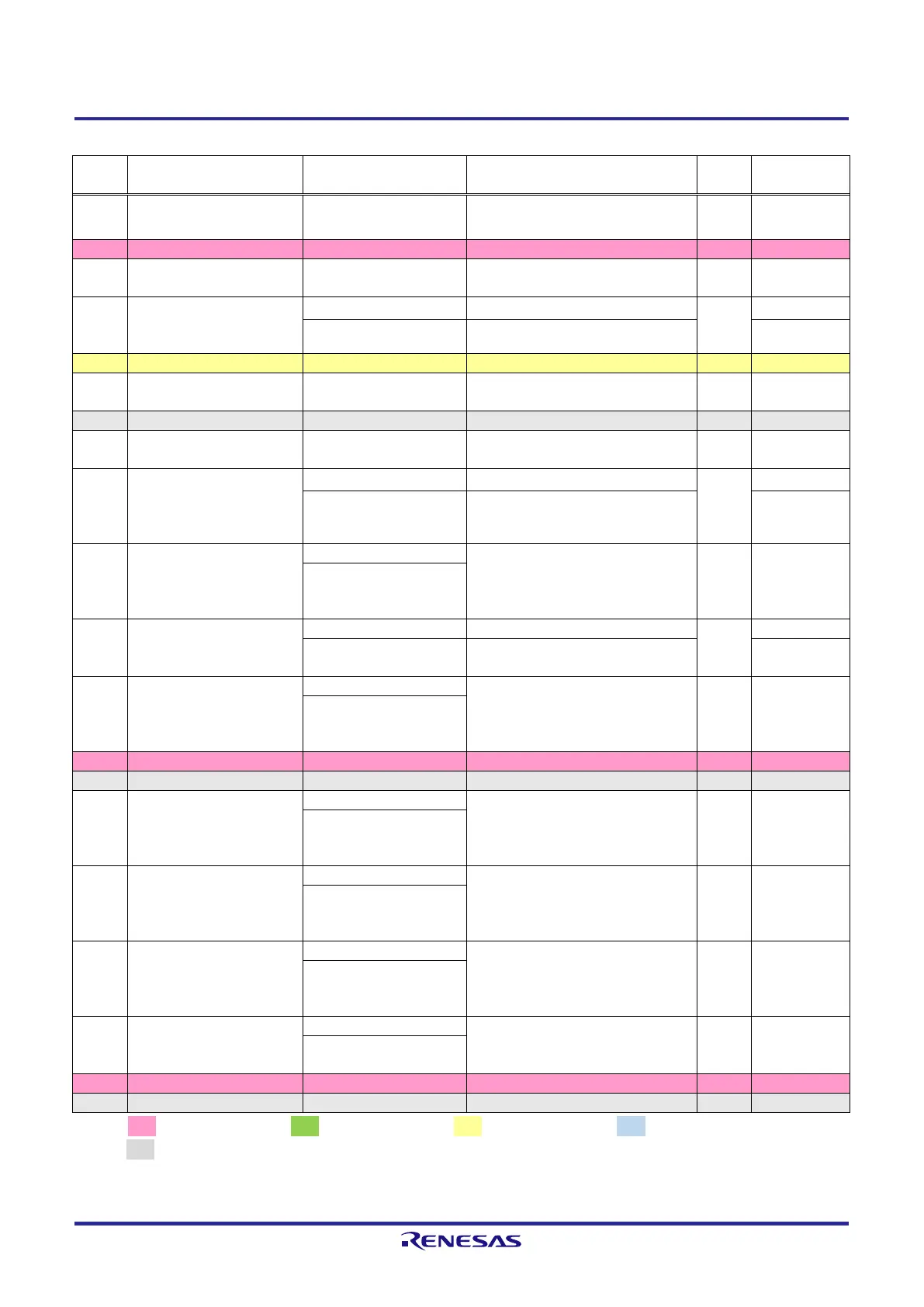
Table 2.2.5 List of RZ/A2M Pin Function Selections Used on the RTK79210XXB00000BE (5)
PD_3 / RIIC1SDA / IRQ3 /
MTCLKD / GTETRGD
Connects to MIPI CSI-2 connector
(CN2 and J1 on the CPU board)
Connects to DIP switch (SW1 on the
CPU board)
P8_1 / A1 / DRP23 /
DV0_DATA16 / GTIOC5B /
IRQ3
Connects to DRP connector (CN2)
Connects to Serial flash memory (U2
on the CPU board)
Connects to Serial flash memory (U2
on the CPU board)
PK_0 /
ET1_TXEN/RMII1_TXDEN
/ NAF3 / CC1_RD0 /
MTIOC1B / SSIBCK2
Connects to Ethernet PHY2 (U28)
Connects to NAND flash memory
(U31)
PF_6 / RTS2 /
DV0_DATA21 /
LCD0_DATA2 / MTIOC6C /
SSITxD0
Connects to digital image input/output
connector (CN15)
PE_0 /
ET0_RXCLK/REF50CK0 /
VIO_FLD / SCK2 / POE4
Connects to Ethernet PHY1 (U27)
Connects to CMOS camera connector
(CN17)
PF_3 / SCK2 /
DV0_DATA18 /
LCD0_DATA5 / MTIOC7D /
SSL10
Connects to digital image input/output
connector (CN15)
PF_0 / SCK3 /
DV0_DATA15 /
LCD0_DATA8 / MTIOC7A /
RSPCK1
Connects to digital image input/output
connector (CN15)
P8_0 / A0 / DV0_DATA14 /
LCD0_DATA9 /
SCI_CTS1/RTS1 /
MTIOC8D
Connects to digital image input/output
connector (CN15)
PA_1 / A17 / DV0_DATA12 /
LCD0_DATA11 /
SCI_RXD1 / MTIOC8B /
IRQ6
Connects to digital image input/output
connector (CN15)
PA_7 / A23 / DV0_DATA6 /
LCD0_DATA17 / SSIRxD1 /
POE10
Connects to digital image input/output
connector (CN15)
[Note] : 3.3V power source, : 1.8V power source, : 1.2V power source, : 3.3V or 1.8V power source,
: GND
Red text CPU board setting display.
 Loading...


