RZ/A2M SUB Board RTK79210XXB00000BE 2. Function specifications
R20UT4398EJ0100 Rev.1.00 2-7
2018.10.11
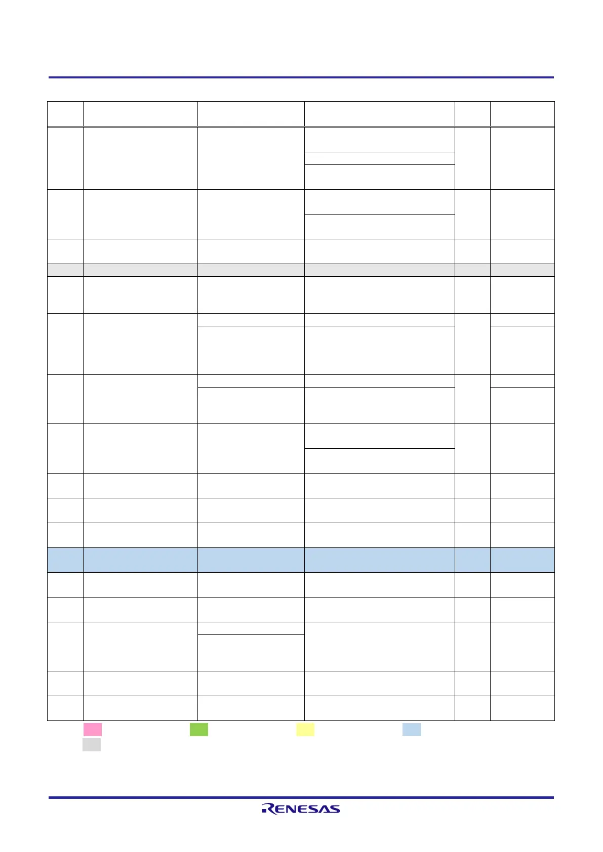
Table 2.2.6 List of RZ/A2M Pin Function Selections Used on the RTK79210XXB00000BE (6)
Connects to CMOS camera connector
(CN17)
Connects to digital image input/output
connector (CN15)
Connects to MIPI CSI-2 connector
(CN2 and J1 on the CPU board)
Connects to USB CC logic controller
(U7 on the CPU board)
PD_1 / RIIC0SDA / IRQ1 /
MTCLKB / GTETRGB
Controls voltage supplied to
PVcc_SD0
PH_3 / HM_RSTO# / RTS2 /
GTIOC6A / MTIOC2A /
SD0_CD / IRQ3
Connects to HyperMCP (U3 on the
CPU board)
PK_3 /
ET1_RXCLK/REF50CK1 /
NAF6 / CC2_RD0 /
CAN0RX_DATARATE_EN /
MOSI0
Connects to Ethernet PHY2 (U28)
Connects to NAND flash memory
(U31)
PK_2 /
ET1_TXD1/RMII1_TXD1 /
NAF5 / VBUSEN1 /
CAN0RX / RSPCK0 / IRQ5
Connects to Ethernet PHY2 (U28)
Connects to NAND flash memory
(U31)
Connects to MIPI CSI-2 connector
(CN2 and J1 on the CPU board)
Connects to USB CC logic controller
(U7 on the CPU board)
PD_2 / RIIC1SCL / IRQ2 /
MTCLKC / GTETRGC
Connects to MIPI CSI-2 connector
(CN2 and J1 on the CPU board)
Connects to UDI connector (CN5 on
the CPU board)
Connects to UDI connector (CN5 on
the CPU board)
Connects to HyperMCP (U3 on the
CPU board)
Connects to HyperMCP (U3 on the
CPU board)
PF_7 / GTETRGD /
DV0_DATA23 /
LCD0_DATA0 / MTCLKD /
IRQ1
Connects to digital image input/output
connector (CN15)
PD_0 / RIIC0SCL / IRQ0 /
MTCLKA / GTETRGA
Connection control for PL_[3:0]
Connects to UDI connector (CN5 on
the CPU board)
[Note] : 3.3V power source, : 1.8V power source, : 1.2V power source, : 3.3V or 1.8V power source,
: GND
Red text CPU board setting display.
 Loading...


