Renesas Starter Kit+ for RZ/T2M 5. User Circuitry
R20UT4939EG0100 Rev. 1.00 Page 18 of 87
Apr 20, 2022
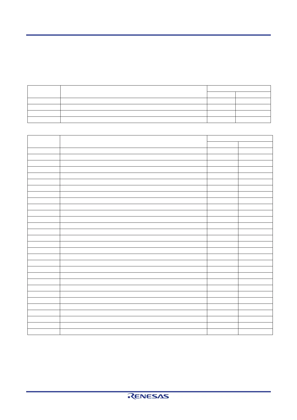
5.3 Switches
There are four push switches and four DIP switches located on the CPU board. The function of each switch
and its connection is shown in Table 5-2 and Table 5-3. For further information regarding switch connectivity,
refer to the CPU board schematics.
Table 5-2: Push Switch Connections
Switch Function
When pressed, the microprocessor is reset.
Connects to IRQ2 for user controls.
Connects to IRQ7 for user controls.
Connects to an NMI input for user controls.
Table 5-3: DIP Switch Connections
Switch Function
Connects to P11_0 for user controls.
Connects to P11_3 for user controls.
Connects to P11_4 for user controls.
Connects to P11_6 for user controls.
Connects to P10_6 for user controls.
Connects to P13_2 for user controls.
Connects to P13_7 for user controls.
Connects to P14_1 for user controls.
Refer to section 6.3 for the setting contents.
Refer to section 6.3 for the setting contents.
Refer to section 6.3 for the setting contents.
Refer to section 6.3 for the setting contents.
Refer to section 6.3 for the setting contents.
Refer to section 6 for the setting contents.
Refer to section 6 for the setting contents.
Refer to section 6 for the setting contents.
Refer to section 6 for the setting contents.
Refer to section 6 for the setting contents.
Refer to section 6 for the setting contents.
Refer to section 6 for the setting contents.
Refer to section 6 for the setting contents.
Refer to section 6 for the setting contents.
Refer to section 6 for the setting contents.
Refer to section 6 for the setting contents.
Refer to section 6 for the setting contents.
Refer to section 6 for the setting contents.
Refer to section 6 for the setting contents.
Refer to section 6 for the setting contents.
Refer to section 6 for the setting contents.
Refer to section 6 for the setting contents.
 Loading...


