Renesas Starter Kit+ for RZ/T2M 6. Configuration
R20UT4939EG0100 Rev. 1.00 Page 31 of 87
Apr 20, 2022
6. Configuration
6.1 Modifying the RSK+
This section lists the option links that are used to modify the way CPU board operates in order to access
different configurations. Configurations are made by modifying link resistors or headers with movable jumpers
or by configuration DIP switches.
A link resistor is a 0Ω surface mount resistor, which is used to short or isolate parts of a circuit. Option links
are listed in the following sections, detailing their function when fitted or removed. Bold, blue text indicates
the default configuration that the CPU board is supplied with. Refer to the component placement diagram
(section 3) to locate the option links, jumpers and DIP switches.
When removing soldered components, always ensure that the CPU board is not exposed to a soldering iron for
intervals greater than 5 seconds. This is to avoid damage to nearby components mounted on the board.
When modifying a link resistor, always check the related option links to ensure there is no possible signal contention or
short circuits. Because many of the MPU’s pins are multiplexed, some of the peripherals must be used exclusively.
Refer to the
RZ/T2M Group User’s Manual: Hardware and CPU board schematics for further information.
6.2 Jumper Settings
Three types of jumpers are provided on the CPU board.
1. Solder bridge
2. Trace cut
3. Traditional pin header jumpers
The following sections describe each type and their default configuration.
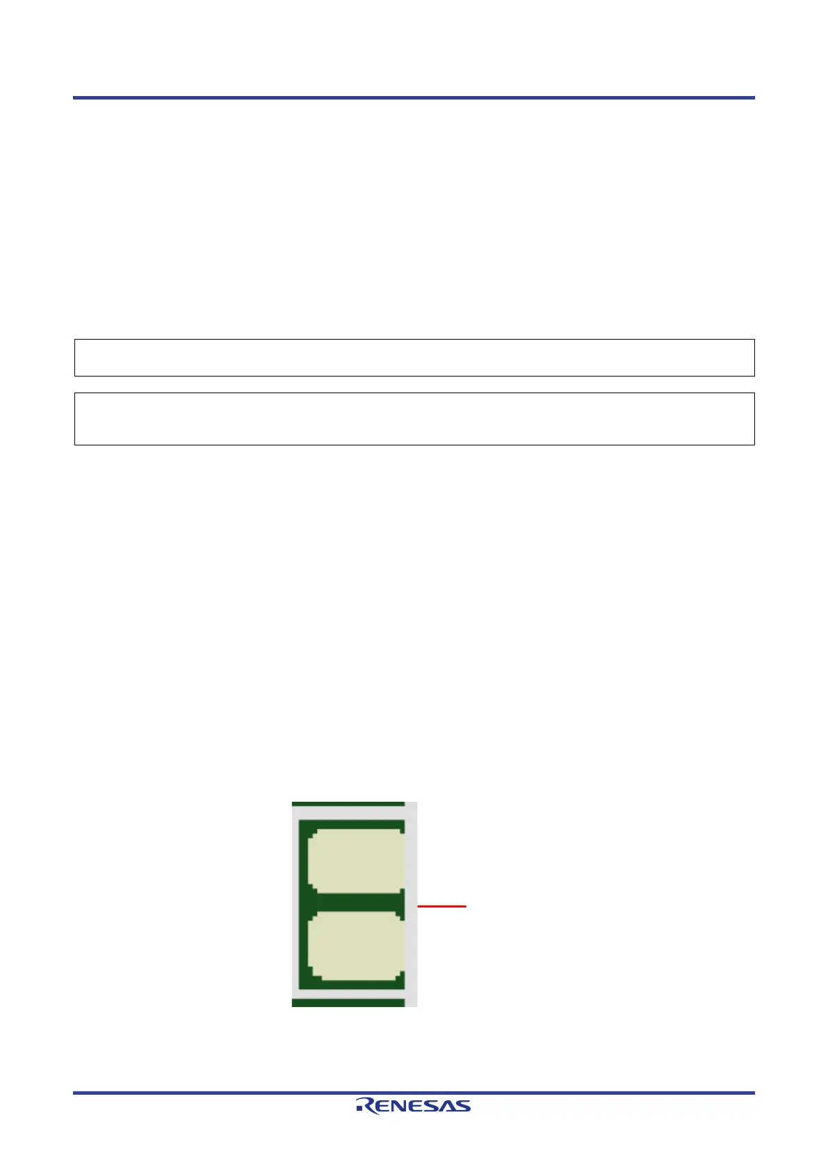
6.2.1 Solder Bridge
A solder-bridge jumper is provided with two isolated pads that may be joined together by one of three
methods:
• Solder may be applied to both pads to develop a bulge on each and the bulges joined by touching a
soldering iron across the two pads.
• A small wire may be placed across the two pads and soldered in place.
• A SMD resistor, size 0805, 0603, or 0402, may be placed across the two pads and soldered in place. A
zero-ohm resistor shorts the pads together.
Figure 6-1: Solder Bridge
 Loading...


