Renesas Starter Kit+ for RZ/T2M 5. User Circuitry
R20UT4939EG0100 Rev. 1.00 Page 20 of 87
Apr 20, 2022
5.6 Pmod™
The RSK+ board is equipped with connectors for Digilent Pmod™ interface. Please connect the Pmod
TM
Peripheral module that is compatible with the PMOD connector.
The Digilent Pmod™ Compatible headers use an SPI interface, an I
2
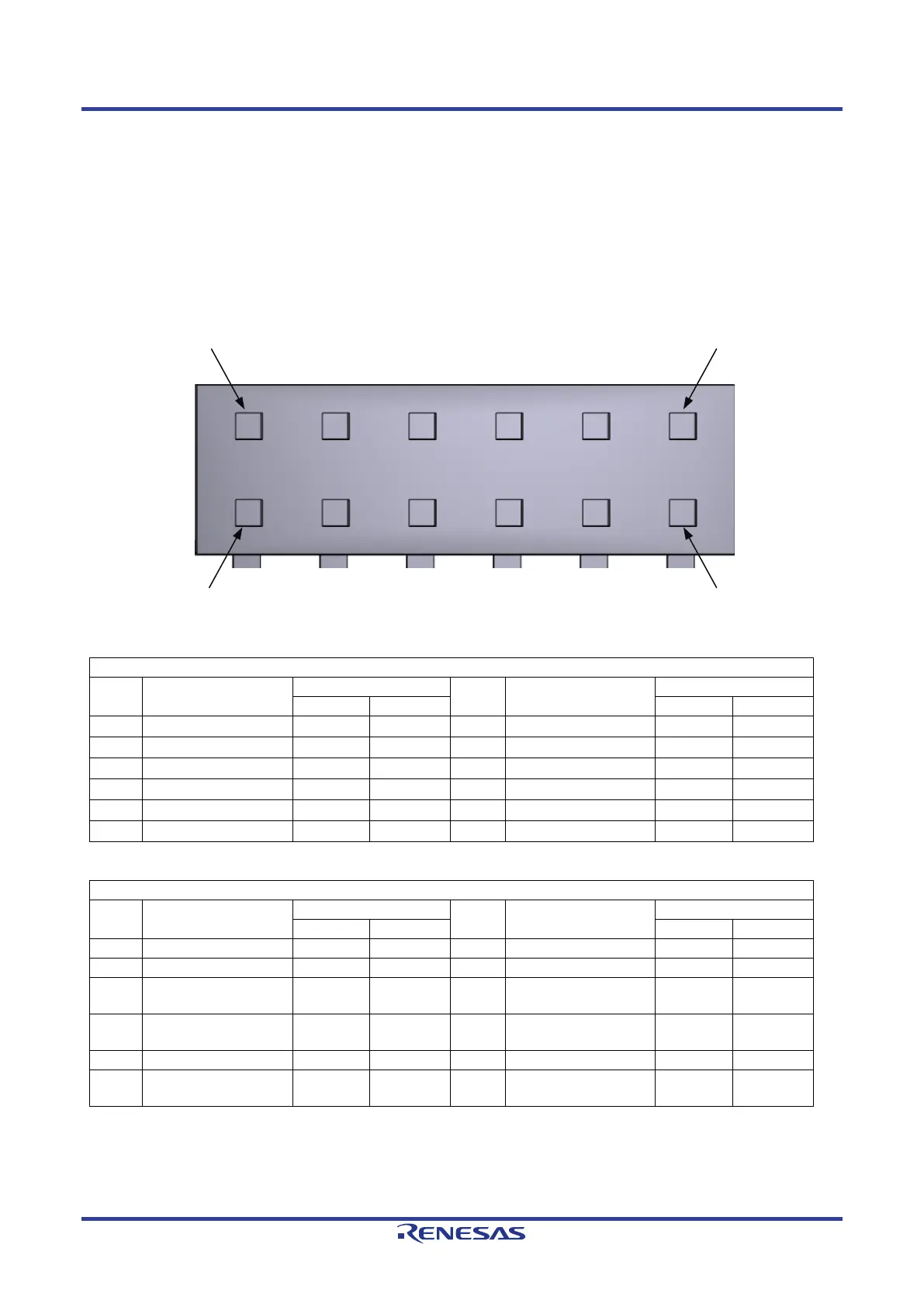
C interface and a UART interface. Figure
5-1 below shows Digilent Pmod™ Compatible Header Pin Numbering. Connection information for the Digilent
Pmod™ Compatible header is provided in Table 5-5 and Table 5-6 below.
Please note that the connector numbering adheres to the Digilent Pmod™ standard and is different from all
other connectors on the RSK+ designs. Details can be found in the Digilent Pmod™ Interface Specification.
Figure 5-1: Digilent Pmod™ Compatible Header Pin Numbering
Table 5-5: Pmod™ Header (J25) Connections
Digilent Pmod™ Compatible Header Connections
Pin Circuit Net Name
Pin Circuit Net Name
Table 5-6: Pmod™ Header (J26) Connections
Digilent Pmod™ Compatible Header Connections
Pin Circuit Net Name
Pin Circuit Net Name
3*
9
P08_3
P19_1
*: It is necessary to set the solder bridge jumper to change the function. Refer to section 6.2 for the required
modifications.
 Loading...


