Renesas Starter Kit+ for RZ/T2M 5. User Circuitry
R20UT4939EG0100 Rev. 1.00 Page 24 of 87
Apr 20, 2022
5.10 USB Serial Port
A USB serial port is implemented in a Renesas low power microcontroller (RL78/G1C) and is connected to the
RZ/T2M Serial Communications Interface (SCI) module. Connections between the USB to Serial converter
and the microprocessor are listed in Table 5-12 below.
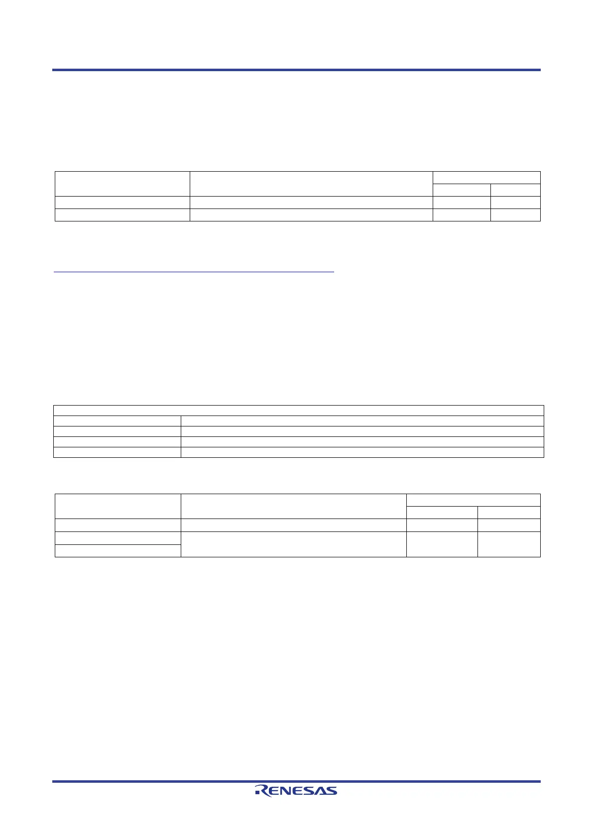
Table 5-12: Serial Port Connections
Signal Name Function
When the CPU board is first connected to a PC running Windows™ with the USB/Serial connection, the PC will look for a
driver. Use the driver that is installed as standard on your PC.
If you do not have the driver, please download the driver installer from the following URL.
https://www.renesas.com/document/rsk-usb-serial-driver?language=en
5.11 Controller Area Network (CAN)
A CAN transceiver IC (U10) is fitted to the RSK+ board and connected to the CAN MPU peripheral. For further
details regarding the CAN protocol and supported modes of operation, please refer to the RZ/T2M Group
User’s Manual: Hardware. Connection information for the CAN interface header is provided in Table 5-13. The
details of connecting to the connected device and MPU are shown in Table 5-14 below.
Table 5-13: CAN Interface Header (J33) Connections
CAN Interface Header Connections
Table 5-14: CAN Connections
CAN Signal Function
CAN Data Reception.
P05_2 P3
*1
: This connection is a not available in the default RSK+ configuration - refer to section 6 for the required
modifications.
 Loading...


