Renesas Starter Kit+ for RZ/T2M 5. User Circuitry
R20UT4939EG0100 Rev. 1.00 Page 30 of 87
Apr 20, 2022
5.18 I
2
C Bus (Inter-IC Bus)
The RZ/T2M features three I
2
C (Inter-IC Bus) interface modules. Channel 0 of the IIC is connected to a 16Kbit
EEPROM. Channel 0 of the IIC is also multiplexed with I
2
C for EtherCAT and can also be used as EEPROM
for EtherCAT. Channel 1 of the IIC is connected to Pmod™ and Grove
®
, QWIIC
®
, mikroBUS™, Application
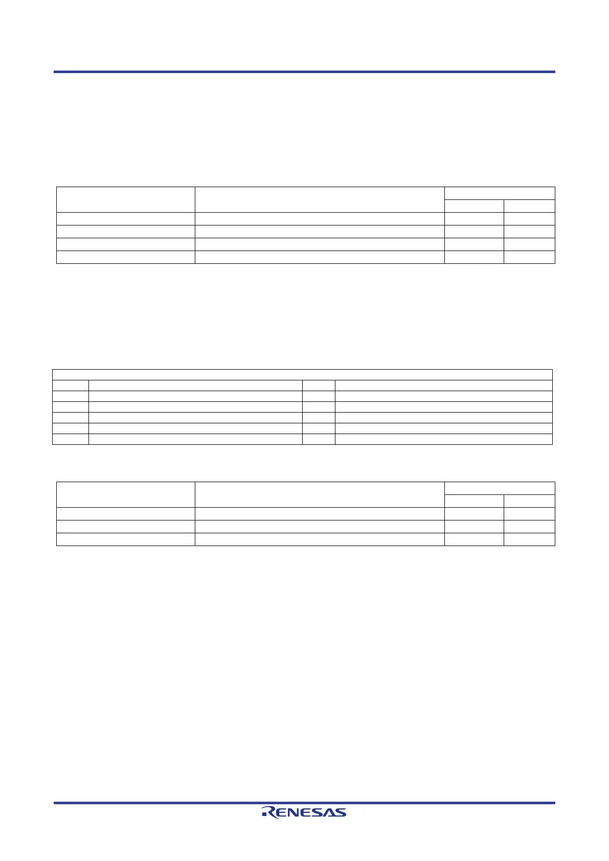
Headers. Table 5-25 below details the connected device, and their connection to the MPU.
Table 5-25: I
2
C BUS Port Connections
Signal Name Function
5.19 RS485 Interface
A RS485 transceiver IC is fitted to the RSK+ board and connected to the SCI MPU peripheral. Connection
information for the RS485 Interface header is provided in Table 5-26 below. The details of connecting to the
connected device and MPU are shown in Table 5-27 below.
Table 5-26: RS485 Interface Header (CN12) Connections
RS485 Interface Header Connections
Table 5-27: RS485 Port Connections
Signal Name Function
SCI3 Driver Enable Signal
*1
: This connection is a not available in the default RSK+ configuration - refer to section 6 for the required
modifications.
 Loading...


