EasyManua.ls Logo

Renesas RZ/T2M

Renesas RZ/T2M
87 pages
To Next Page IconTo Next Page
To Previous Page IconTo Previous Page
Loading...
Renesas Starter Kit+ for RZ/T2M 7. Headers
R20UT4939EG0100 Rev. 1.00 Page 79 of 87
Apr 20, 2022
7.2 Pin Headers
This RSK+ board is equipped with a header that connects specific MPU pins separately from the application
headers.
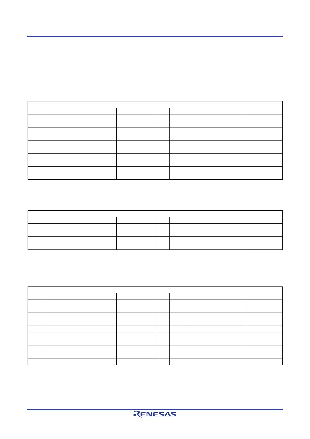
Table 7-6 below lists the connections of the Pin header, CN1. The encoder interface signal of the MPU is
connected to the Pin header, CN1.
Table 7-6: Pin Header CN1 Connections
Pin Header CN1
Pin
Circuit Net Name
MPU Pin
Pin
Circuit Net Name
MPU Pin
1
ENCIF0
E2
2
ADTRG_ENCIF_RSPCK
F2
3
ENCIF2
J6
4
M2_ENCZ
J5
5
GROUND
-
6
ENCIF4
G1
7
ENCIF5
H19
8
CTS3#
J16
9
USB_OVRCUR
H18
10
GROUND
-
11
ENCIF8
K6
12
IRQ11_ENCIF9_WAIT#
K3
13
ENCIF10
L5
14
ENCIF11
A4
15
3.3V
-
16
ENCIF12
N3
17
CAN_RX
P3
18
CAN_TX
P2
19
MISO2
E19
20
5.0V
-
Table 7-7 below lists the connections of the Pin header, CN2.
Table 7-7: Pin Header CN2 Connections
Pin Header CN2
Pin
Circuit Net Name
MPU Pin
Pin
Circuit Net Name
MPU Pin
1
ETHSW_LPI0
V5
2
TDI
H2
3
TMS
H3
4
TCK
J2
5
MISO2
E19
6
GTIOC16B
E9
7
LED_LED6
V6
8
P08_3
T6
Table 7-8 below lists the connections of the Pin header, CN3. The ΔΣ interface signal of the MPU is
connected to the Pin header, CN3.
Table 7-8: Pin Header CN3 Connections
Pin Header CN3
Pin
Circuit Net Name
MPU Pin
Pin
Circuit Net Name
MPU Pin
1
5.0V
-
2
3.3V
-
3
ESC_RESETOUT# (MCLK5)
E10
4
ETH_LED5 (MDAT5)
A9
5
EEPROM_SCL (MCLK4)
F10
6
EEPROM_SDA (MDAT4)
C10
7
TRACE_D6 (MCLK3)
B7
8
TRACE_D7 (MDAT3)
B6
9
GROUND
-
10
GROUND
-
11
5.0V
-
12
3.3V
-
13
TRACE_D4 (MCLK2)
A7
14
M1_UP (MDAT2)
J18, L3
15
TRACE_D2 (MCLK1)
B8
16
TRACE_D3 (MDAT1)
A6
17
TRACE_D0 (MCLK0)
B9
18
TRACE_D1 (MDAT0)
C8
19
GROUND
-
20
GROUND
-

Table of Contents

Other manuals for Renesas RZ/T2M

Related product manuals