32
Installation – NCi-4 interface
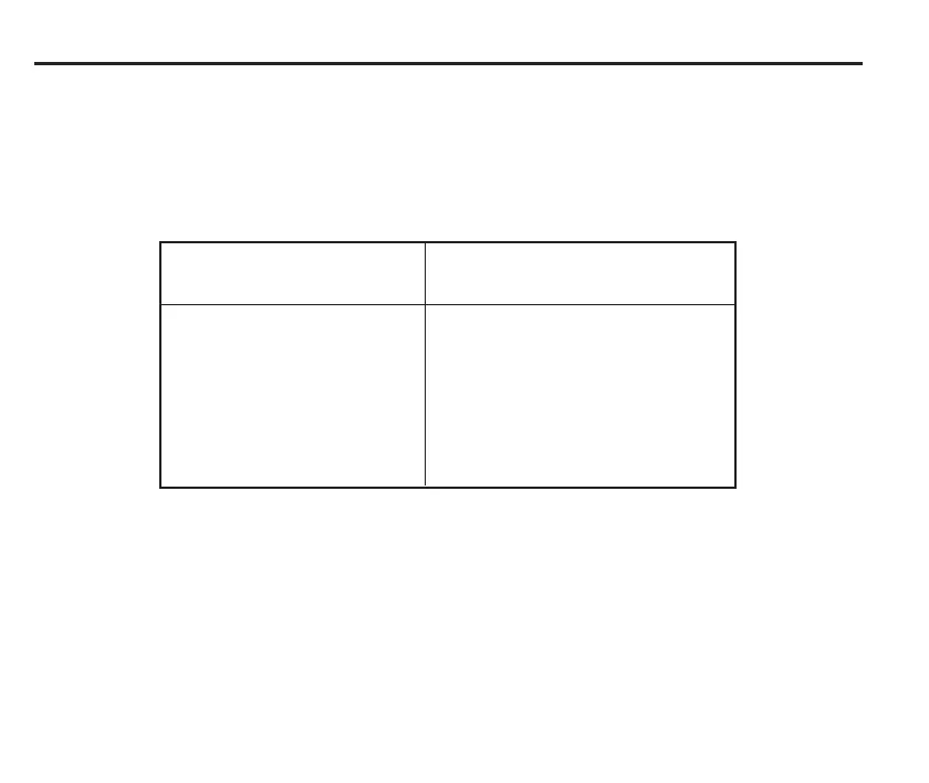
NC4 wiring details
The colour and intended function of each of the
wires from the NC4 transmitter and receiver units
are described below.
✸ Note that as this wire is not used, you should
ensure that the free end is correctly insulated.
NC4 Tx unit NC4 Rx unit
Wire colour Function Wire colour Function
Green Screen Green Screen
Black 0 V Black 0 V
Red 12 V Red 12 V
White
not used
✸ White Analogue output 1
Blue
not used
✸ Blue Analogue output 2
Purple
not used
✸ Purple Set-up
Grey Probe status Grey Probe status
What to do next
After you have finished installing the NCi-4
interface, apply electrical power to the interface.
After the interface has been powered, switch on
the air supply and set the air pressure.
 Loading...