54
XL laser system
XL-80 hardware XL-80 applications
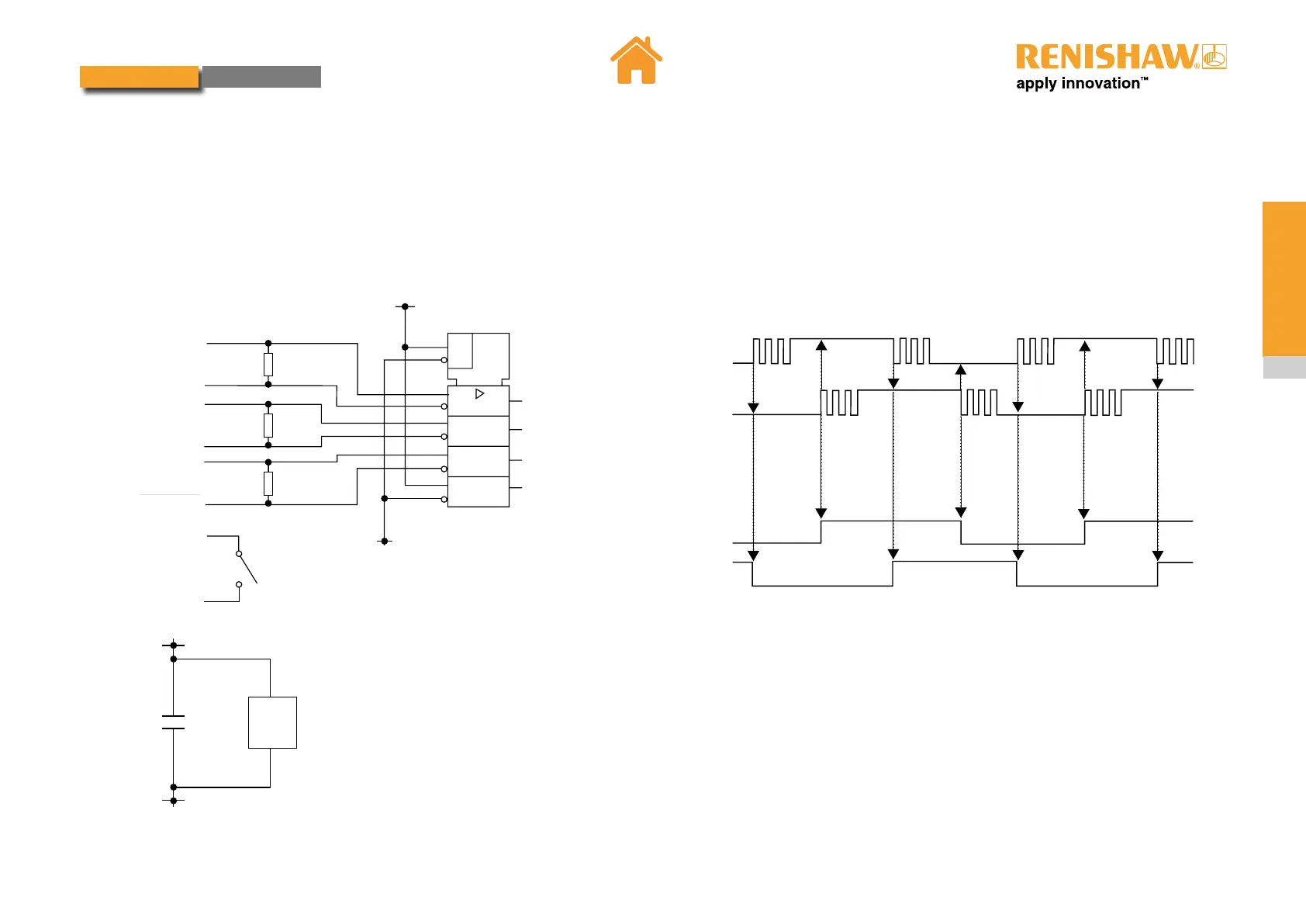
RS422 receiver circuitry
The image below shows a recommended circuit for the user end of RS422 receivers.
A, B and ALARMOUT signals should be DC terminated with 100W - 120W resistor.
100R
100R
100R
ALARMOUT
A
__
A
B
__
B
ALARMOUT
DATUM
SWITCH
4
12
2
1
6
7
10
9
14
15
0
V
0
V
EN
=1
IC1
AQUAD
BQUAD
ERTIN
3.3 V
10 nF
16
8
0
V
IC1
IC1 = MAXIM MAX3096
Recommended RS422 receiver
Hysteresis
Electrical noise or axis vibration can cause multiple edges to appear at each
quadrature transition as shown below, even when stationary.
Hysteresis disabled
Hysteresis enabled
AQuad
AQuad
BQuad
BQuad
If a fast counter is not available, hysteresis may be applied (DIP switch 3 on), to
clean up the edges so that only a single transition occurs each time. Note this
will introduce one unit of resolution (10 nm / 80 nm) positional hystersis when the
direction of travel is reversed.
 Loading...