22
eRev. [Major Version]1.01.0 8/9/2023
KrosFlo® KR2i Real-Time Process Management (RPM™) System
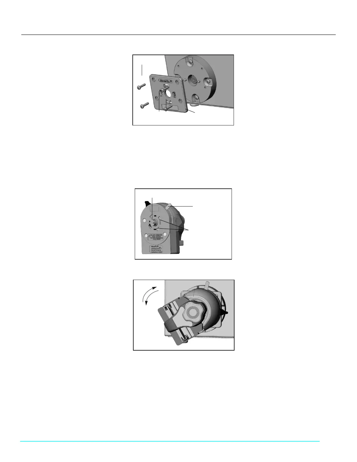
Figure 7. Attaching mounting plate to drive
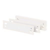
2. Orient the pump head with its back facing the drive and insert the tang on the pump head shaft into the shaft’s slot on the
drive. Align the bayonet features on the back of the pump head with the bayonet tabs on the front of the mounting plate
(see Figures 8–10).
• The pump head should be tilted about 30° counterclockwise from the intended installed orientation.
• Press pump head firmly against the drive and rotate clockwise until no more rotation is possible (see Figure 10).
The bayonet lock lever will automatically snap toward the back of the pump, locking it to the mounting plate.
Figure 8. Back of Research II Pump Head to drive
Figure 9. Position for engaging bayonet feature for horizontal mounting
Pump Shaft with Tang
B
ayonet Lock
Lever, locked
from rear position
Bayonet Features
Approximately 30°