30
eRev. [Major Version]1.01.0 8/9/2023
KrosFlo® KR2i Real-Time Process Management (RPM™) System
Figure 28. Detector Cable in sample compartment
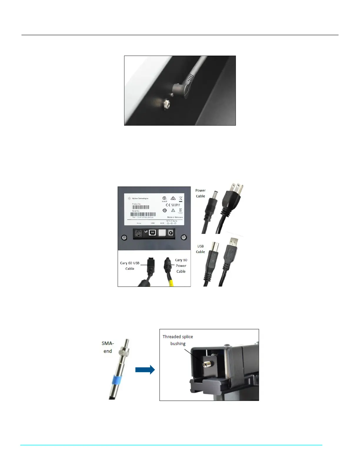
3. Connect the Cary 60 power cable (supplied with the Cary 60) to the back of the Cary 60. Then connect the plug to an
approved outlet (see Figure 30).
4. Connect the Cary 60 USB cable, (supplied with the Cary 60) to the back panel of the Cary 60. Connect the other end to a
USB port on the computer (see Figure 30).
Figure 29. Cary 60 power cable and USB cable, back panel
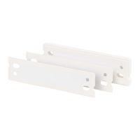
5. Connect the SMA end of the Delivery Fiber to the threaded splice bushing at the back of the Fiber Optic Coupler. Use the
hex nut to securely tighten the connection.
Figure 30. Fiber Optic Coupler threaded splice bushing