4. Connect one (if using KR2i) or up to two (if using KMPi) Automatic Backpressure Valves
(ABV's) to the Auxiliary Component Octopus Cable's "Valve 1" ("Valve" for KR2i) and/or
"Valve 2" (see Section 10.3 for ABV Setup details)
5. Connect power cable to the TFF system
6. Follow guidelines and diagrams below to determine which Auxiliary Components are
required to operate specific Pump Modes for manual, semi-automated, and automated
processes (see Section 8 for Pump Mode Setup details)
i. If using Auxiliary Pump, configure Auxiliary Pump before starting application (see
Section 10.2 for Auxiliary Pump Setup details)
ii. After connecting Auxiliary Components, power on the TFF system first before
powering on Auxiliary Components
7. Connect TFF flowpath to TFF system
8. Set low and high pressure alarms and interlocks as required by the process conditions
9. Input Concentration Factor/Diafiltration Volume (CF/DV) set-points into the TFF system’s
Pump Mode settings to start application
Auxiliary Components Required for Pump Modes
Pump Mode Feed Scale Permeate Scale Auxiliary Pump 1 Auxiliary Pump 2
M Mode
C Mode X*
X
X**
C/D Mode X X X X**
C/D/C Mode X X X X
C/D/D/C Mode X X X X
CFC Mode X X X X**
CF/D/C Mode X X X X
Ctrl Mode X X X**
* The Feed Scale is only required in applications using C Mode if user does not want to input
starting Feed Scale values
** Auxiliary Pump 2 is optional for applications that utilize it as a Permate Pump, such as MF
applications
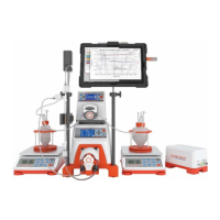
NOTE: All diagrams in Section 7 are shown with the process-scaled KMPi, however the same set-ups
may be used with the KR2i.

 Loading...