en
11
InstallationIndications, functions and optionsMessages Commissioning Operation and function
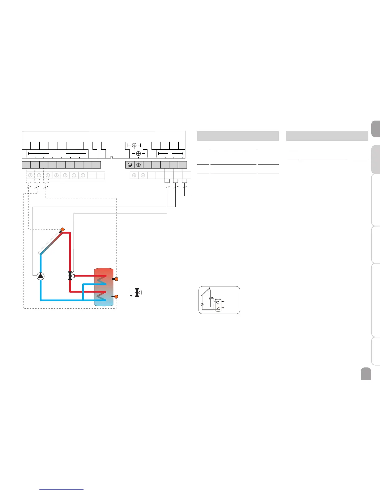
System 4: Solar system with 1 store and 3-port valve for store loading in layers
The controller compares the temperature at sensor S1 to the temperatures at
sensors S2 and S3. If the measured temperature differences are higher than the
adjusted switch-on temperature differences, the pump (R1) will be activated and the
corresponding store zone will be loaded up to the adjusted store maximum or set
temperature respectively via the valve (R2). The priority logic effects prior loading
of the upper zone of the store.
System 4 system screen
Temperature sensors
S1 Temperature collector 1 / GND
S2 Temperature store
base
2 / GND
S3 Temperature store top 3 / GND
S4 Free 4 / GND
Relay
R1 Solar pump R1 / N / PE
R2 Valve Solar R2 / N / PE
R4 Free R4 / R4
R2
R1
S3
S2
S1
N N N N
10 11
332
2 2
3
VBus
VBus
V40
S4
S3
GND
Sensors
Relais
S2
S1
N
R2
R1
L
R4
R4
R2 R1 L
1234
56789
PWM A
PWM B
Mains
Flow direction when
normally open

 Loading...