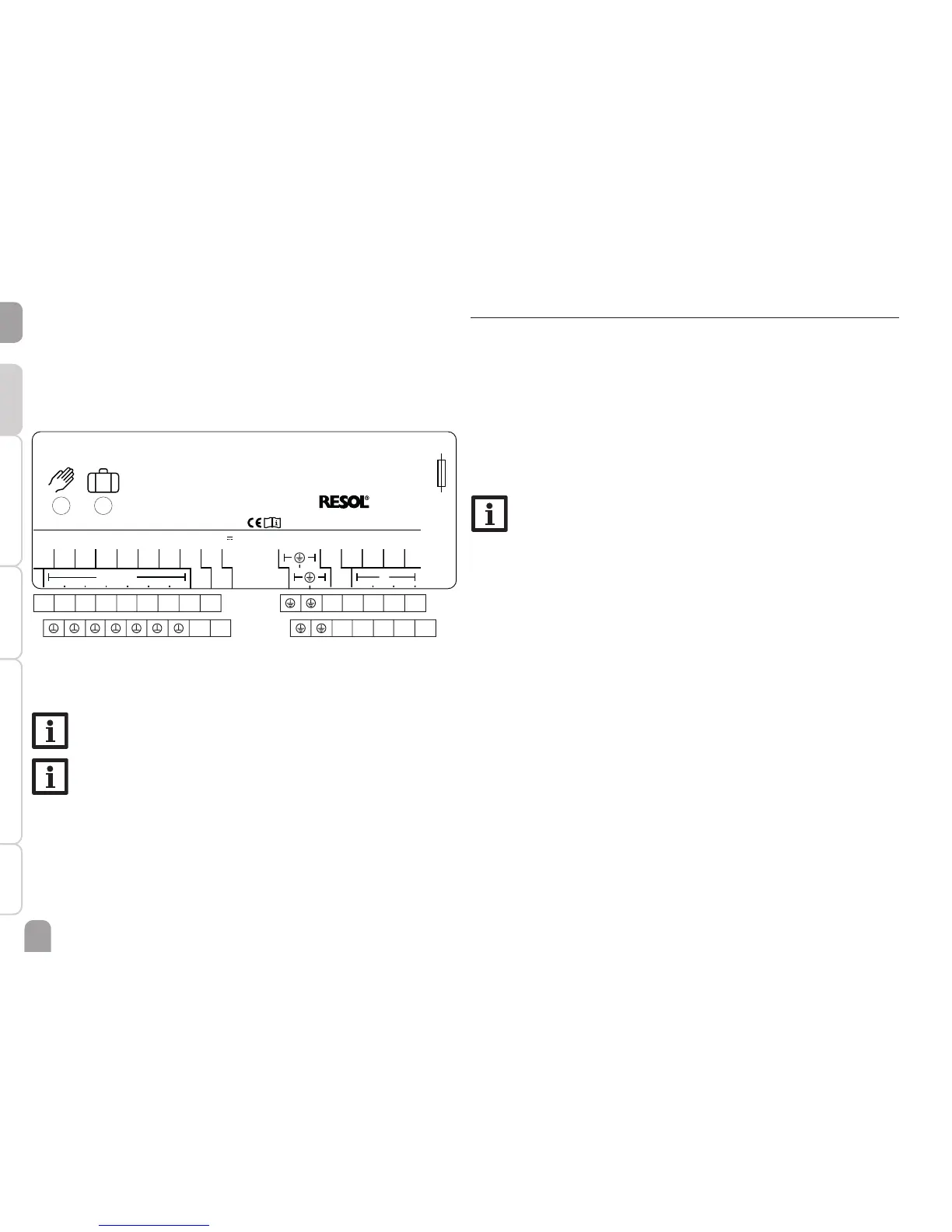
A V40 owmeter can be connected to the terminals V40 and GND (either polarity).
The terminals marked PWM are control outputs for a high-efciency pump (see
page 18).
Relay allocation for PWM outputs:
PWM A - Relay 1
PWM B - Relay 2
VBus
VBus
V40
S4
S3
GND
DeltaSol
®
SLL
Made in Germany
Sensors
S2
S1
100 ... 240 V
T2A
50-60 Hz
N
R2
R1
L
R1-R2|1 (1) A 240 V~
R4|1 (1) A 30V
IP 20
R4
PWM
A
PWM B
R4
N N N N
R2 R1 L
1234
56789
10 11
The mains connection is at the terminals:
Neutral conductor N
Conductor L
Protective conductor ⏚
Note
The connection depends on the system layout selected (see page 7).
Note
For more details about the initial commissioning procedure see page 23.
2.3 Data communication / Bus
The controller is equipped with the RESOL VBus
®
for data transfer and energy
supply to external modules. The connection is to be carried out at the two termi-
nals marked VBus (any polarity).
One or more RESOL VBus
®
modules can be connected via this data bus, such as:
• RESOL DL2 Datalogger
• RESOL DL3 Datalogger
Furthermore, the controller can be connected to a PC or integrated into a network
via the RESOL VBus
®
/USB or VBus
®
/LAN interface adapter (not included). Different
solutions for visualisation and remote parameterisation are available on the RESOL
website www.resol.com.
Note
More accessories on page 55.

 Loading...