Operator’s Manual, RAMP
®
1.6.5 Initial Start-up
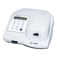
The power button is located on the back panel of the Reader (Figure
on, the Reader performs a Power
certain pre-
set parameters. The POST includes calibration verification, optical system verification,
real-
time clock test, transport movement test, and a bat
battery at the time of the POST). If the measured battery voltage is low, a warning message appears
on the LCD along with an audible alarm. If this occurs, the Reader should be plugged into an AC
outlet using t
NOTE: A fully-
charged battery will allow approximately 100 tests to be run before re
charging is required. In the event that a Reader is
low. It takes approximately 24 hours to fully rechar
may be operated with the AC Adapter during battery recharging. Refer to Section
recommended battery care.
NOTE: Ensure
that the battery is sufficiently charged or that the Reader is connected to an
AC outlet prior to performing a test.
outlet once the test has started
The Reader can also function in an enhanced control
function. This requires the setting of a Master P.I.N., which provides controlled access to the
SYSTEM SETTINGS Menu.
Functions available through the SYSTEM SETTINGS Menu include
changing the instrument clock, s
operator data, erasing data, selecting print settings, test counters, erasing memory, and setting QC
timers. The User Lock-
out mode ensures that only operators with a valid controlled P.I.N
to run tests on the Reader.
To operate the Reader with User Lock
by setting a Master P.I.N. (Section
(Section 2.6.4).
NOTE: Ensure that
operators have read and understood the Operator’s Manu
Test Kit Instructions for Use
1.6.6
If using a printer, connect it to the Reader via the RS
See Appendix A
for printer compatibility information.
If the Reader is connected to a computer or another Reader, ensure that the serial connect
properly secured. See
CAUTION!
If using the optional Barcode Wand accessory, ensure that it is properly
connected to the Reader via the Barcode Wand connector port on the
turning the Reader on. Failure to do so may result in damage to the Barcode Wand.
The power button is located on the back panel of the Reader (Figure
1-2
). When the power is turn
on, the Reader performs a Power
-On Self-
Test (“POST”) to ensure the system is operating within
set parameters. The POST includes calibration verification, optical system verification,
time clock test, transport movement test, and a bat
tery test (if the Reader is operating on the
battery at the time of the POST). If the measured battery voltage is low, a warning message appears
on the LCD along with an audible alarm. If this occurs, the Reader should be plugged into an AC
charged battery will allow approximately 100 tests to be run before re
charging is required. In the event that a Reader is
left
on for 24 hours, the battery may run
low. It takes approximately 24 hours to fully rechar
ge the battery, however, the Reader
may be operated with the AC Adapter during battery recharging. Refer to Section
recommended battery care.
that the battery is sufficiently charged or that the Reader is connected to an
AC outlet prior to performing a test.
Do not connect or disconnect the Reader from an AC
outlet once the test has started
.
The Reader can also function in an enhanced control
led
manner by enabling the “User Lock
function. This requires the setting of a Master P.I.N., which provides controlled access to the
Functions available through the SYSTEM SETTINGS Menu include
changing the instrument clock, s
etting and enabling User IDs and associated P.I.N.s, transferring
operator data, erasing data, selecting print settings, test counters, erasing memory, and setting QC
out mode ensures that only operators with a valid controlled P.I.N
To operate the Reader with User Lock
-
out, ensure the SYSTEM SETTINGS Menu has limited access
by setting a Master P.I.N. (Section
2.6.2
) and that a User ID and P.I.N. are defined for each operator
operators have read and understood the Operator’s Manu
Test Kit Instructions for Use
before attempting to perform a test.
If using a printer, connect it to the Reader via the RS
-
232 serial port on the back panel (Figure
for printer compatibility information.
If the Reader is connected to a computer or another Reader, ensure that the serial connect
for serial port compatibility information.
If using the optional Barcode Wand accessory, ensure that it is properly
connected to the Reader via the Barcode Wand connector port on the
turning the Reader on. Failure to do so may result in damage to the Barcode Wand.
Introduction
7
). When the power is turn
ed
Test (“POST”) to ensure the system is operating within
set parameters. The POST includes calibration verification, optical system verification,
tery test (if the Reader is operating on the
battery at the time of the POST). If the measured battery voltage is low, a warning message appears
on the LCD along with an audible alarm. If this occurs, the Reader should be plugged into an AC
charged battery will allow approximately 100 tests to be run before re
-
on for 24 hours, the battery may run
ge the battery, however, the Reader
may be operated with the AC Adapter during battery recharging. Refer to Section
3.3 for
that the battery is sufficiently charged or that the Reader is connected to an
Do not connect or disconnect the Reader from an AC
manner by enabling the “User Lock
-out”
function. This requires the setting of a Master P.I.N., which provides controlled access to the
Functions available through the SYSTEM SETTINGS Menu include
etting and enabling User IDs and associated P.I.N.s, transferring
operator data, erasing data, selecting print settings, test counters, erasing memory, and setting QC
out mode ensures that only operators with a valid controlled P.I.N
. are allowed
out, ensure the SYSTEM SETTINGS Menu has limited access
) and that a User ID and P.I.N. are defined for each operator
operators have read and understood the Operator’s Manu
al and the
232 serial port on the back panel (Figure
1-2).
If the Reader is connected to a computer or another Reader, ensure that the serial connect
ion is
If using the optional Barcode Wand accessory, ensure that it is properly
turning the Reader on. Failure to do so may result in damage to the Barcode Wand.