Description Symbol Unit HCS03.1E-
W0070-_-05
HCS03.1E-
W0100-_-05
HCS03.1E-
W0150-_-05
HCS03.1E-
W0210-_-05
Output voltage (UL) U
out
V 3 x AC 0...480
Output current (UL) I
out
A 45,0 75,0 95,0 145,0
Output frequency range (UL)
13)
f
out
Hz 0...1600
Power dissipation at continuous cur‐
rent and continuous DC bus power
respectively (UL)
14)
P
Diss_cont
W 800,00 950,00 1150,00 2000,00
Last modification: 2010-08-04
1) 2) 3) Housing dimension; see also related dimensional drawing
4) 5) 6) See fig. "Air Intake and Air Outlet at Device"
7) Observe supply voltage for motor holding brakes
8) HMS, HMD, HCS plus motor holding brake and control section;
HCS01 including control section
9) DC bus L+, L-; mains input L1, L2, L3
10) Use listed AC input line fuses (class J; 600 V AC) or listed circuit
breakers (600 V AC) at the mains supply
11) Copper wire; PVC-insulation (conductor temperature 70 °C); installa‐
tion method B1; table 6
12) Copper wire; PVC-insulation (conductor temperature 90 °C); ta‐
ble 28.1; Ta ≤ 40 °C
13) Depending on switching frequency which was set in parameter
P‑0‑0001
14) Plus dissipation of braking resistor and control section
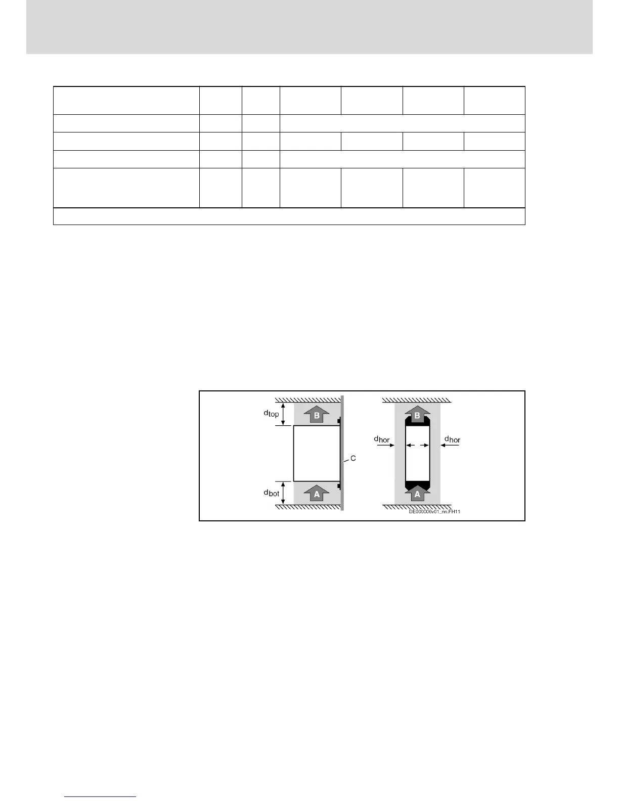
Fig.3-1: HCS - UL Ratings and Dimensions
Distances
A Air intake
B Air outlet
C Mounting surface in control cabinet
d
top
Distance top
d
bot
Distance bottom
d
hor
Distance horizontal
Fig.3-2: Air Intake and Air Outlet at Device
Bosch Rexroth AG DOK-INDRV*-HCS03******-IT01-EN-P
Rexroth IndraDrive Drive Controllers Power Sections HCS03
24/67
Ratings and Dimensions