Before working on live parts: De-energize installation and secure power
switch against unintentional or unauthorized re-energization.
Wait at least 30 minutes after switching off the supply voltages to allow dis‐
charging.
Check whether voltage has fallen below 50 V before touching live parts!
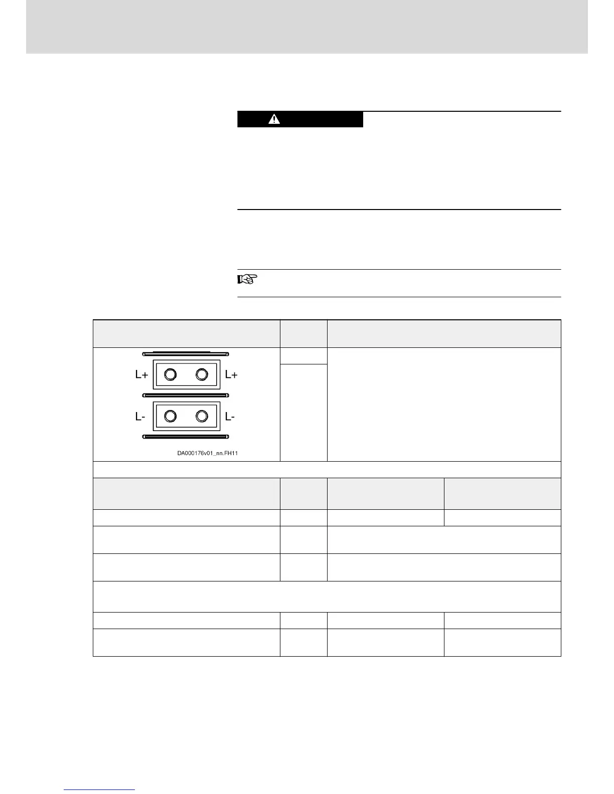
Function, Pin Assignment
The DC bus connection connects
● several drive controllers to one another
● a drive controller to additional components
HCS02.1E-W0012 drive controllers do not have a DC bus con‐
nection.
Technical Data of the Connection Point
View Identifica‐
tion
Function
L+ Connection points for connecting DC bus connections
L-
Screw connection
M6 thread at device (terminal block)
Unit Min. Max.
Tightening torque Nm 5,5 6,5
Short circuit protection Via fusing elements connected in the incoming circuit to the
mains connection
Overload protection Via fusing elements connected in the incoming circuit to the
mains connection
Current carrying capacity "looping through" from L+ to L+, L- to L-
(contact bars in scope of supply of accessory HAS01)
With contact bars -072 A 220
Additionally with contact bars ‑042 and end
piece
A 245
Fig.5-14: Function, Pin Assignment, Properties
DOK-INDRV*-HCS03******-IT01-EN-P
Rexroth IndraDrive Drive Controllers Power Sections HCS03
Bosch Rexroth AG 41/67
Instructions for Use