Tightening torque Nm 5,5 6,5
Power consumption W P
N3
(see technical data)
Voltage load capacity V U
N3
(see technical data)
Polarity reversal protection Within the allowed voltage range by internal protective diode
Current carrying capacity "looping through" from 24V to 24V, 0V to 0V
(contact bars in scope of supply of accessory HAS01)
With contact bars -072 A 220
Fig.5-12: Function, Pin Assignment, Properties
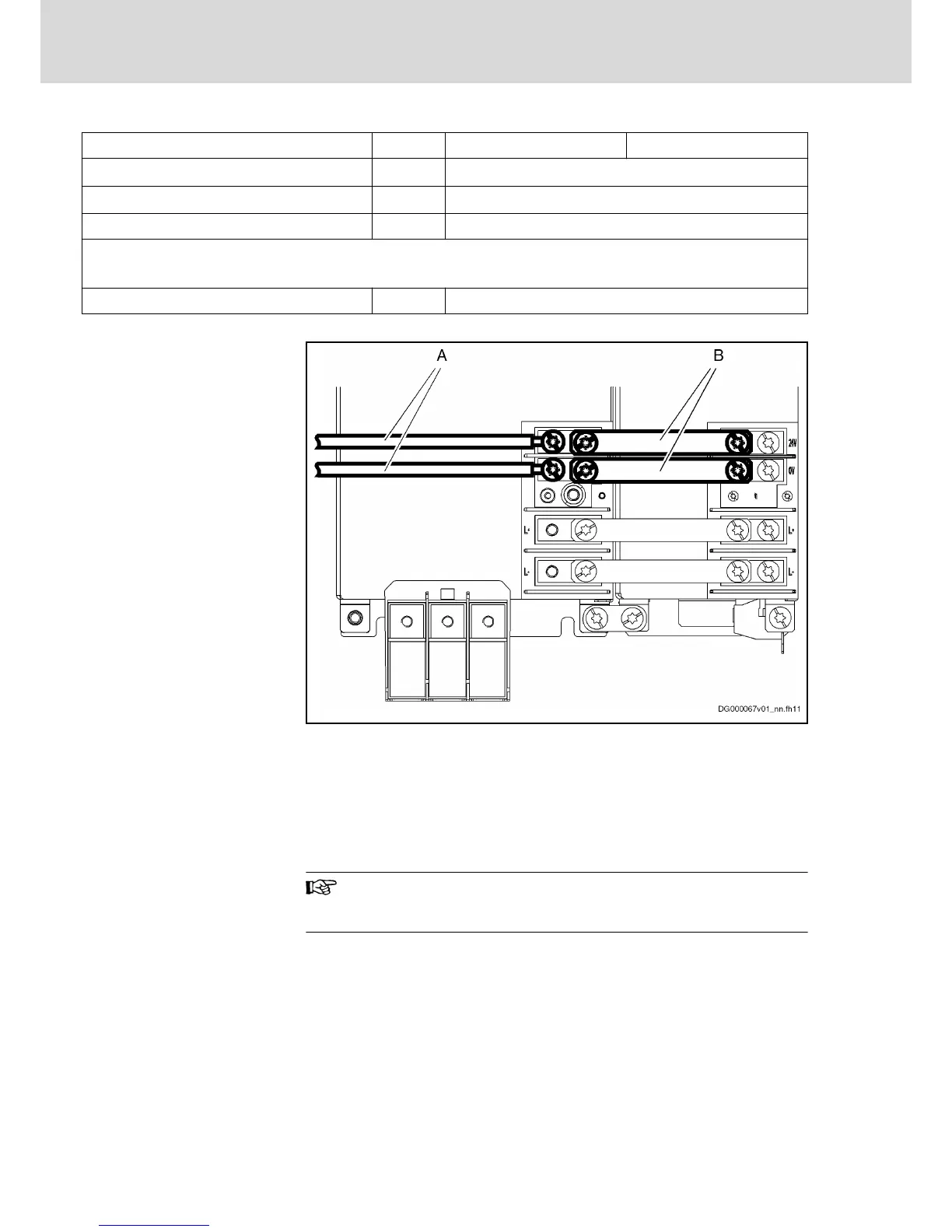
Connection Diagram
A Cable (to source of control voltage supply)
B Contact bars
Fig.5-13: Connection Points and Connections of Control Voltage
Notes on Installation
Requirements on the connection to the 24V supply:
● Maximum allowed inductance of 100 µH (2 twisted single strands, 75 m
long)
● Parallel line routing where possible
The input 0V is connected in conductive form to the housing po‐
tential. It is therefore impossible to use an insulation monitor at
+24V and 0V against housing.
Bosch Rexroth AG DOK-INDRV*-HCS03******-IT01-EN-P
Rexroth IndraDrive Drive Controllers Power Sections HCS03
40/67
Instructions for Use