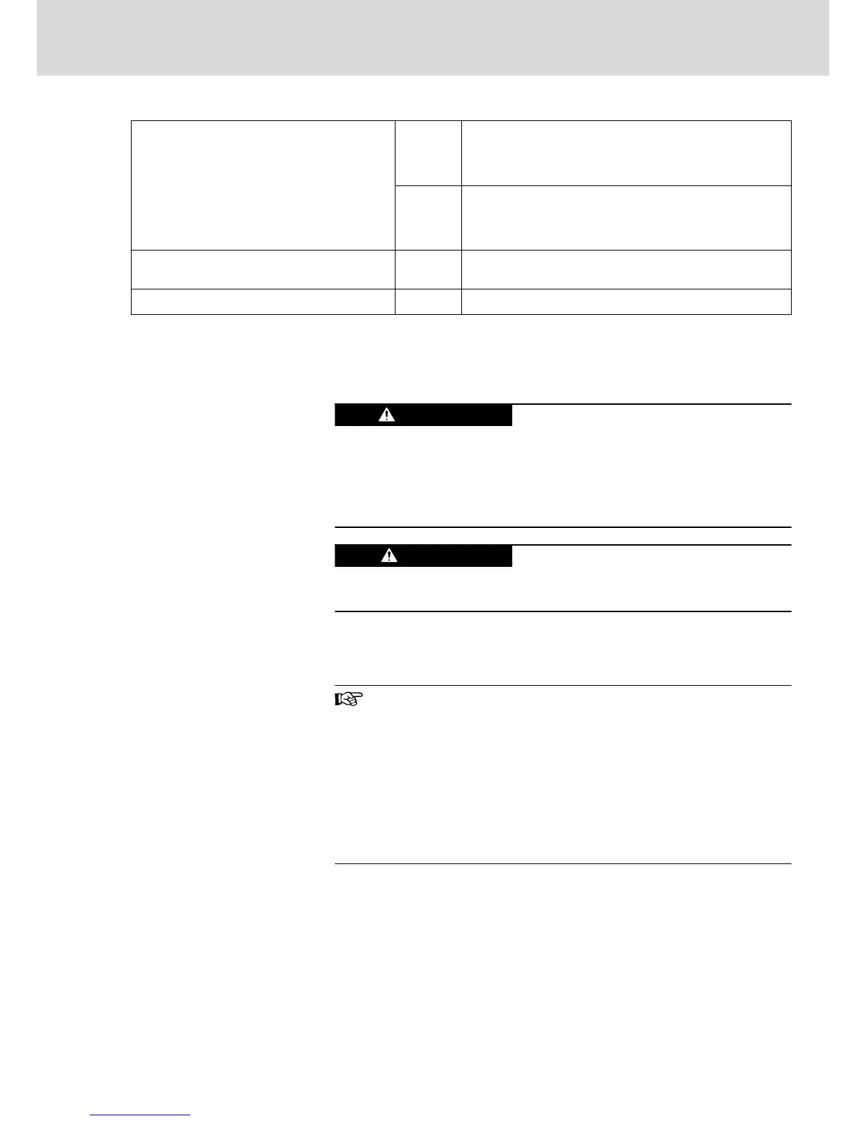
Connection cables
Stranded wire with ring cable lug
mm
2
1×16; 1×25; 1×35; 1×50
2×25; 2×35; 2×50
2×16 with accessories
AWG 1×6; 1×4; 1×2; 1×1
2×4; 2×2; 2×1
2×6 with accessories
Occurring current load and minimum required
connection cross section
A See technical data of device used (I
LN
and A
LN
)
Occurring voltage load V See technical data of device used (U
LN
or U
LN_nenn
)
Fig.5-5: Function, Pin Assignment, Properties
5.2.4 X5, Motor Connection
Important Notes
Lethal electric shock by live parts with more
than 50 V!
Exclusively operate the device
● with plugged on connectors (even if there haven't been any lines con‐
nected to the connectors) and
● with connected equipment grounding conductor!
Damage to the device!
Provide strain relief for the terminal connectors of the device in the control
cabinet or use the optionally available connection accessory HAS02.
Notes on Installation
The indicated connection cross sections are the cross sections which can be
connected. Dimension the required cross section of the connecting lines ac‐
cording to the occurring current load.
● For optimum shield contact of the motor power cable, use
our accessory HAS02, where possible.
● For the connection between drive controller and motor use
our ready-made motor power cables, where possible (see
documentation "Rexroth Connection Cables").
● When using NFD03.1 mains filters, the maximum allowed
conductor cross section is limited to 4 mm
2
.
● For selecting the motor cables, observe the information con‐
tained in the Project Planning Manual "Rexroth IndraDrive
Drive System" → "Connection Cables to Motor".
DOK-INDRV*-HCS03******-IT01-EN-P
Rexroth IndraDrive Drive Controllers Power Sections HCS03
Bosch Rexroth AG 33/67
Instructions for Use