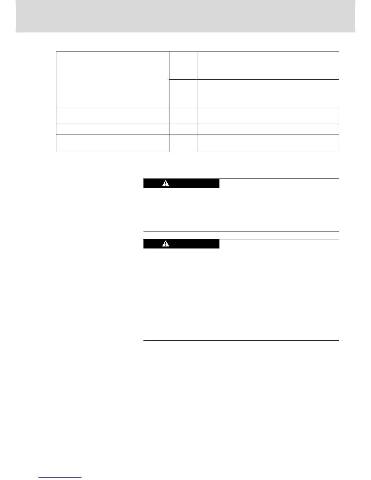
Connection cables
Stranded wire with ring cable lug
mm
2
1×16; 1×25; 1×35; 1×50
2×25; 2×35; 2×50
2×16 with accessories
AWG 1×6; 1×4; 1×2; 1×1
2×4; 2×2; 2×1
2×6 with accessories
Occurring current load and minimum required
connection cross section
A See technical data of device used (I
out
)
Occurring voltage load V See technical data of device used (U
out
)
Short circuit protection A1, A2, A3 against each other and each of them against
ground
Fig.5-7: Function, Pin Assignment, Properties
5.2.5 X6, Motor Temperature Monitoring and Motor Holding Brake
Lethal electric shock by live parts with more
than 50 V!
Exclusively operate the device
● with plugged on connectors (even if there haven't been any lines con‐
nected to the connectors) and
● with connected equipment grounding conductor!
Dangerous movements! Danger to persons
from falling or dropping axes!
The standard motor holding brake provided or an external motor holding
brake controlled directly by the drive controller are not sufficient on their own
to guarantee personal safety!
Personal safety must be achieved using higher-level, fail-safe measures:
● Block off danger zones with safety fences or safety guards
● Additionally secure vertical axes against falling or dropping after switch‐
ing off the motor power by, for example,
– mechanically securing the vertical axes
– adding external braking/arrester/clamping mechanisms
– ensuring sufficient equilibration of the vertical axes
Function
The connection point X6 contains the connections for
● monitoring the motor temperature
● controlling the motor holding brake
DOK-INDRV*-HCS03******-IT01-EN-P
Rexroth IndraDrive Drive Controllers Power Sections HCS03
Bosch Rexroth AG 35/67
Instructions for Use