Via an integrated contact element (BR), the power section
switches the voltage of the external 24V supply (connection X13
at HCS02 power sections) to the output for controlling the motor
holding brake.
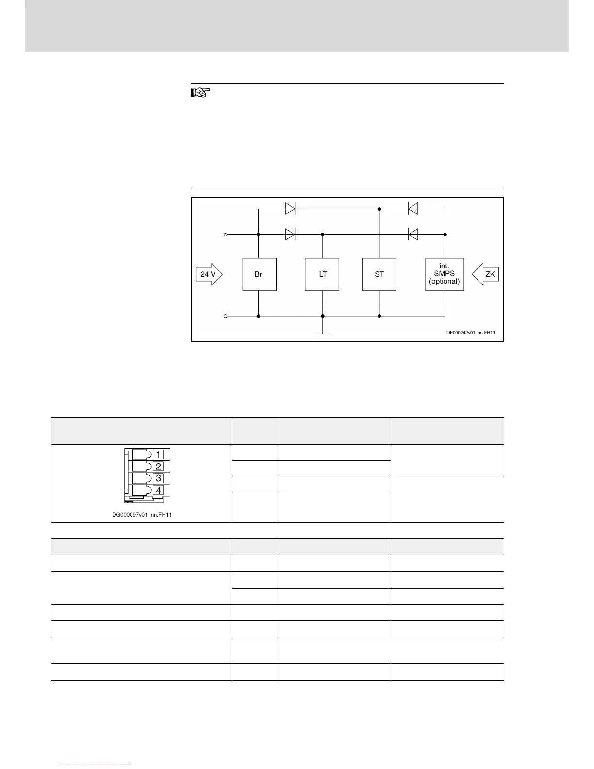
The integrated 24V control voltage supply of power sections of
the order code ‑NxxV is not available at the connection point X6
(see figure below "Block Diagram of Internal Control Voltage").
Therefore, an external 24V supply is required for controlling the
motor holding brake.
BR Circuit for brake control
LT Power section, e.g. HCS02
ST Control section, e.g. CSB01
int. SMPS For types HCS0x.1E-Wxxxx-NxxV: Internal switched-mode power
supply
ZK DC bus
Fig.5-8: Block Diagram of Internal Control Voltage
View Connec‐
tion
Signal name Function
1 MotTemp+ Input motor temperature
evaluation
2 MotTemp-
3 +24V Output for controlling the mo‐
tor holding brake
4 0V
Spring terminal (connector) Unit Min. Max.
Connection cable solid wire
mm
2
0,5 1,5
Connection cable stranded wire
mm
2
0,5 1,5
AWG 20 16
Current carrying capacity X6.3, X6.4:
HCS03.1E-W0070; ‑W0100; ‑W0150; ‑W0210 A - 2
Number of switching actions of integrated con‐
tact element for controlling motor holding brake
HCS03: Wear-free electronic contact
Time constant of load
1)
ms - 50
Bosch Rexroth AG DOK-INDRV*-HCS03******-IT01-EN-P
Rexroth IndraDrive Drive Controllers Power Sections HCS03
36/67
Instructions for Use