11
RPB-IOM (06-22) 131782-B
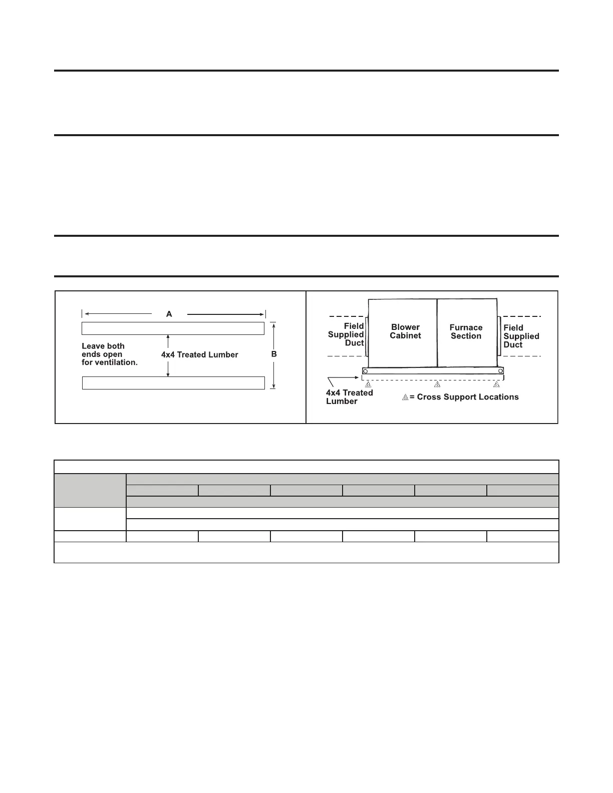
Field-Supplied Support Structure
NOTE: If considering this type of installation in snow areas, it is recommended that the 4 × 4
wooden rails underneath the system be on a cross-support structure at least 12 inches higher
than the roof surface. Whether the supports are mounted directly on the roof or placed up on an
additional structure, the horizontal length of the system should be supported by two 4 × 4 treated
wooden rails.
1. Cut treated 4 × 4 wooden rails for length in accordance with dimension A (see Figure 4, DETAIL A).
2. Space rails in accordance with dimension B (see Figure 4, DETAIL A) so that curb cap skirt fits over edge of
boards with rails sitting inside horizontal length of curb cap. If rails are being laid directly on roof, position them
as shown in Figure 4, DETAIL A).
3. If rails are not being placed directly on roof surface, install cross-supports underneath rails at ends of unit and
at all cabinet joints: between blower cabinet and furnace section and between furnace and optional downturn
plenum (see Figure 4, DETAIL B).
NOTE: The field-supplied, weather-resistant cross-support structure must be adequate for the
weight of the system. Cross-supports should run the entire width of the system to support the
rails at the recommended locations (see Figure 4, DETAIL A).
Figure 4. Field-Supplied Curb Assembly (Refer to Table 8)
DETAIL B
DETAIL A
Table 8. Field-Supplied Curb Dimensions
Dimension
(See Figure 4)
Unit Size
125 150, 175 200, 225 250, 300 350 400
Inches (mm)
A
60-5/8 (1540)
84-9/16 (2148)*
B 24-5/16 (618) 29-13/16 (757) 35-5/16 (897) 43-9/16 (1106) 49-1/16 (1246) 54-1/2 (1384)
*With downturn plenum (option AQ5 or AQ8). Although dimensions are included for units with a downturn plenum cabinet, it is strongly
recommended that a full roof curb be used on an installation with a downturn plenum cabinet and/or a bottom return air duct.