37
RPB-IOM (06-22) 131782-B
Table 18. High Elevation Burner Orifices
Installation
Altitude
(Feet (Meters))
Installation
Location
Unit Size
Natural Gas Propane
PN Orifice Size PN Orifice Size
2001–3000
(611–915)
US
125, 175, 225, 300, 350, 400 84437 #42 11834 #54
150,250 38678 #45 11830 #55
200 11833 #44 11830 #55
2001–4500
(611–1373)
Canada
125, 175, 225, 300, 350, 400 11828 #43 11834 #54
150,250 38678 #45 11830 #55
200 11833 #44 11830 #55
3001–4000
(916–1220)
US
125, 175, 225, 300, 350, 400 11828 #43 11834 #54
150,250 38678 #45 11830 #55
200 11833 #44 11830 #55
4001–5000
(1221–1525)
US
125, 175, 225, 300, 350, 400 11828 #43 11834 #54
150,250 38678 #45 11830 #55
200 11833 #44 11830 #55
5001–6000
(1526–1830)
US
125, 175, 225, 300, 350, 400 11828 #43 97360 1.35 mm
150,250 16590 #46 39658 #56
200 38678 #45 39658 #56
6001–7000
(1831–2135)
US
125, 175, 225, 300, 350, 400 11833 #44 97360 1.35 mm
150,250 84853 #47 39658 #56
200 38678 #45 39658 #56
7001–8000
(2136–2440)
US
125, 175, 225, 300, 350, 400 11833 #44 11830 #55
150,250 84853 #47 39658 #56
200 16590 #46 39658 #56
8001–9000
(2441–2745)
US
125, 175, 225, 300, 350, 400 38678 #45 11830 #55
150, 250 40414 #48 39658 #56
200 84853 #47 39658 #56
9001–10,000
(2746–3045)
US
125, 175, 225 16590 #46 11830 #55
150, 250 40414 #48 39658 #56
200 84853 #47 39658 #56
300, 350, 400 38678 #45 11830 #55
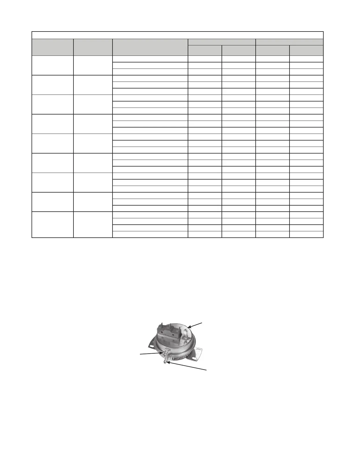
SETSCREW ON FRONT OF SWITCH
MUST BE MANUALLY ADJUSTED
WHILE UNIT IS OPERATING
NEGATIVE PRESSURE CONNECTION
ON FRONT OR TOP OF SWITCH
SENSES BLOWER SIDE OF FILTERS
POSITIVE PRESSURE CONNECTION
ON BACK OR BOTTOM OF SWITCH
SENSES AIR INLET SIDE OF FILTERS
Dirty Filter Switch Adjustment
After the unit is started but before continuous operation, the dirty filter switch must be set as follows:
1. With clean filters in place, blower doors closed, and blower operating, decrease pressure setting by adjusting
setscrew on switch (see Figure 20) clockwise until indicator light is energized or setscrew is bottomed out.
2. At that point, adjust setscrew three full turns counterclockwise or until setscrew is top-ended.
3. At that setpoint, indicator light will be activated at approximately 50% filter blockage.
Figure 20. Dirty Filter Switch