25
RPB-IOM (06-22) 131782-B
Optional Ductstat with Electronic Remote Setpoint Module (Option AG15)
• The field-installed sensing probe is field-wired to the remote temperature selector shown in Figure 12, which has
a temperature operating range to 130°F. The remote modules and sensing probe are shipped separately for field-
installation. Follow the wiring diagram provided with the unit and the manufacturer’s instructions for wiring and
installation. One module is for selecting temperature and one module is a one-stage adder module.
⚠ CAUTION ⚠
Ensure that the heat/cool selector switch on the remote temperature selector is positioned to Heat.
Optional Electronic Modulation
NOTE: Unit sizes 350 and 400 with electronic modulation require a minimum natural gas supply
pressure of 6 IN WC.
The type and capability of the electronic modulation system depends on the option selected. Electronic modulation
options are identified by a suffix to the serial No. printed on the heater rating plate. AG7 is identified as MV-1, AG8
is identified as MV-3, AG9 is identified as MV-4, AG21 is identified as MV-A, AG39 is identified as MP-1, and AG40
is identified as MP-2.
Electronic Modulation Between 50% and 100% Firing Rate (Option AG7, AG8, or AG9)
• Depending on the heat requirements established by the thermistor sensor, the burner modulates between 100%
and 50% firing. The thermistor is a resistor that is temperature-sensitive in that as the surrounding temperature
changes, the Ohms resistance changes through the thermistor. This change is monitored by the solid-state control
center (amplifier) that furnishes varying DC current to the modulating valve to adjust the gas input.
• Each modulating valve is basically a regulator with the electrical means of raising and lowering the discharge
pressure. When no DC current is fed to this device, it functions as a gas pressure regulator to supply 3.5 IN WC
pressure to the combination gas valve.
• Refer to the wiring diagram provided with the furnace for proper wiring connections.
• Electronic modulation for heating that is controlled by a specially-designed room thermostat (60–85°F) is identified
as option AG7.
• Electronic modulation for makeup air application that is controlled by a duct sensor and temperature selector
(55–90°F) is identified as option AG8 or AG9. The temperature selector setting for option AG8 is on the amplifier
(see Figure 13). Option AG9 has a remote temperature selector. Both systems are available with an override
thermostat.
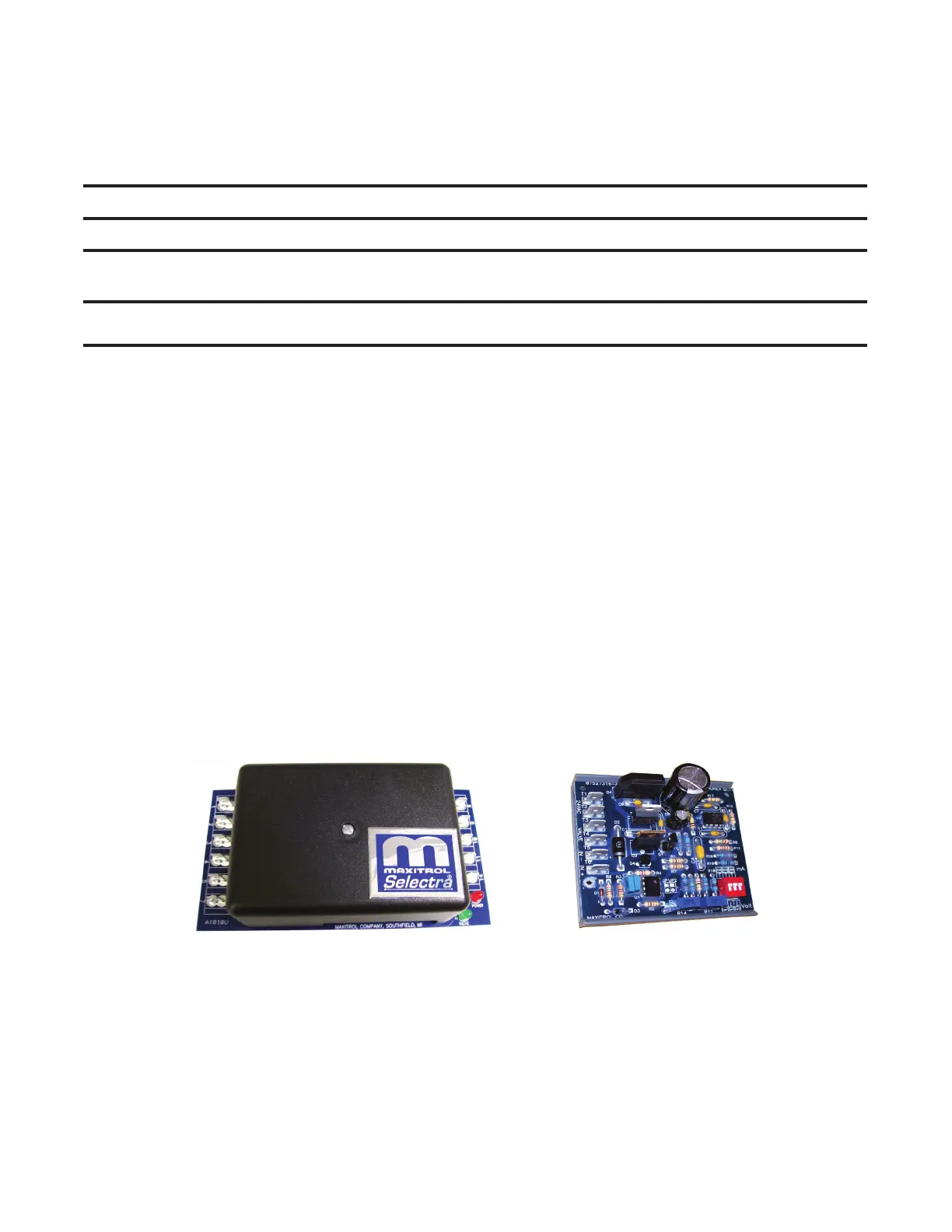
AMPLIFIER SIGNAL CONDITIONER
Figure 13. Maxitrol Amplifier and Signal Conditioner