40
RPB-IOM (06-22) 131782-B
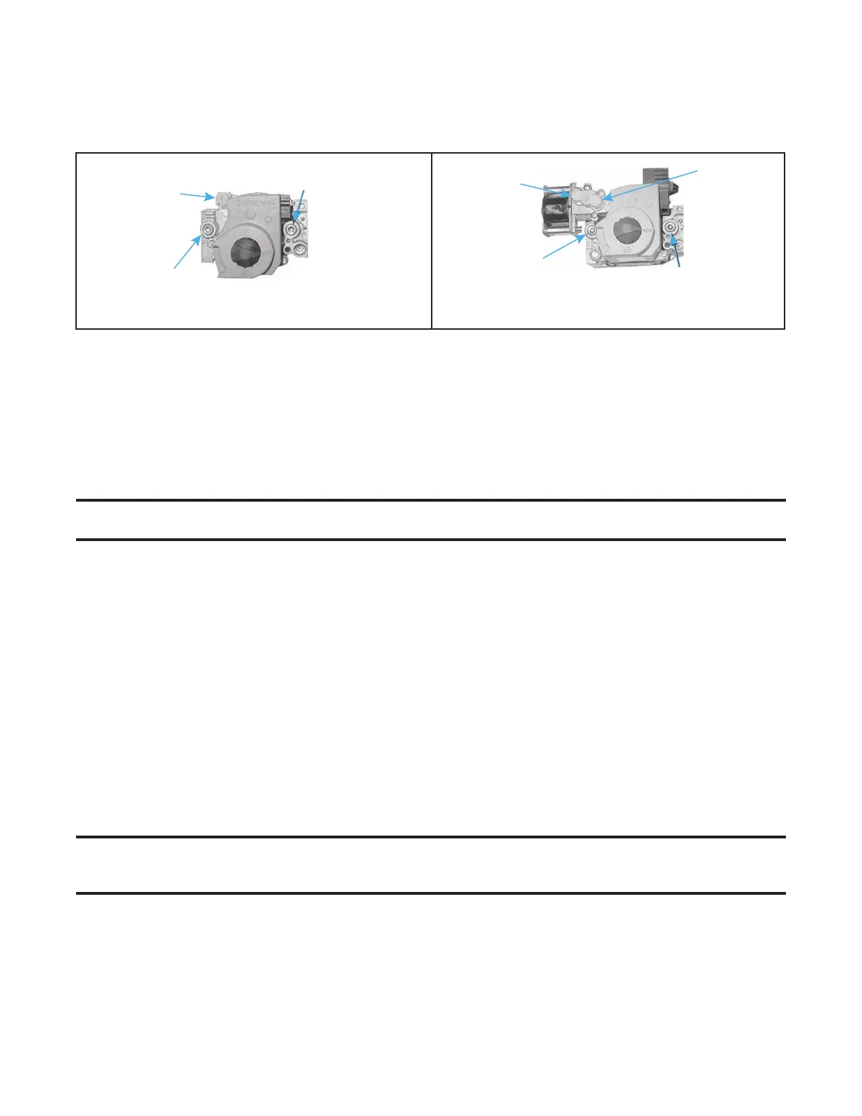
SINGLE-STAGE VALVE
1/8-INCH INLET
PRESSURE TAP
1/8-INCH OUTLET
PRESSURE TAP
1/8-INCH OUTLET
PRESSURE TAP
TWO-STAGE VALV E
1/8-INCH INLET
PRESSURE TAP
HIGH FIRE
REGULATOR
ADJUSTING
SCREW
LOW FIRE
REGULATOR
ADJUSTING
SCREW
REGULATOR
ADJUSTING
SCREW
MAINTENANCE—CONTINUED
Maintenance Procedures—Continued
Combination Gas Valve Maintenance—Continued
Figure 22. Combination Gas Valve Test Connections
3. With field-installed manual valve closed, turn up thermostat to fire unit and to allow unit to go through one trial
for ignition.
4. Reset thermostat to shut OFF unit and observe manometer for 2 to 3 minutes for indication of gas pressure. No
pressure should be indicated on manometer. If manometer indicates gas pressure, field-installed manual gas
valve must be replaced or repaired before combination gas valve can be checked.
5. If manometer does not indicate gas pressure, slowly open field-installed manual gas valve. After manometer
indicates that gas pressure has reached equilibrium, close manual shutoff valve.
NOTE: Refer to Gas Supply Pressure section for operational pressure settings and instructions
for checking pressure settings.
6. Observe gas pressure on manometer. There should be no loss of gas pressure. If manometer indicates loss of
gas pressure, replace combination gas valve before placing heater in operation.
Burner Rack Maintenance
Remove, disassemble, clean, reassemble, and re-install burner rack as follows:
1. Remove burner rack:
a. Turn OFF gas and electric supply.
b. Remove control access side panel.
c. Disconnect any pilot lines and flame sensor leads.
d. Mark and disconnect electric valve leads.
e. Uncouple union in gas supply.
f. Remove sheet metal screws in top corners of burner rack assembly.
g. Pull drawer-type burner rack out of furnace.
2. Disassemble burner rack:
NOTE: Natural gas burner racks manufactured before MAR 1995 may have a lighter tube carryover
system. Break the lighter tube connection at the orifice and remove the supply tubing, the drip
shield, and the lighter tube.
a. For natural gas burner rack, remove flash carryover system from manifold end of burner rack.
b. For propane gas burner rack:
(1) Break lighter tube connection at regulator and remove lighter tube orifice supply tubing.
(2) Remove retaining screws in drip shield and remove shield.
(3) Remove retaining screws and slide out lighter tube.