26
RPB-IOM (06-22) 131782-B
CONTROLS—CONTINUED
Optional Electronic Modulation—Continued
Computer-Controlled Electronic Modulation Between 50% and 100% Firing Rate (Option AG21)
• With option AG21, the furnace is equipped with a Maxitrol signal conditioner (see Figure 13) that operates much
the same way as the amplifier above to control the regulator valve. The signal conditioner accepts an input signal
of either 4–20 milliamps or 0–10V from a customer-supplied control device such as a computer.
• With the dip switches on the conditioner positioned to ON, the conditioner accepts a 4–20 milliamp signal. With
the dip switches on the conditioner positioned to OFF, the conditioner accepts a 0–10V signal. The conditioner
converts the signal to the 0–20V DC current required to control the modulating valve.
Electronic Modulation Between 20–28% and 100% Firing Rate (Option AG39)
NOTE: Option AG39 is available only with natural gas and is not available on unit size 350.
• Depending on its size, a furnace equipped with option AG39 has a 20–28% turndown ratio. The furnace will ignite
at any input rate in the available range and will maintain average thermal efficiencies equal to or greater than the
thermal efficiency at full fire.
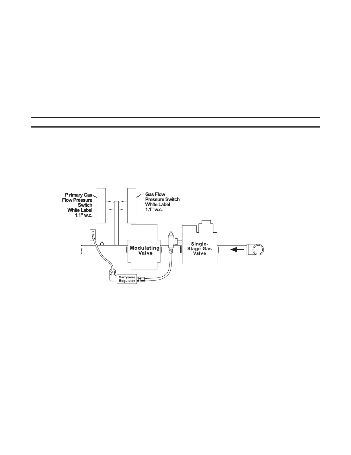
• The gas train (see Figure 14) includes a single-stage gas valve, a modulating valve, and two gas pressure switches.
The burner rack is equipped with one flash carryover and a regulated gas lighter tube system. The carryover lighter
tube receives its gas supply through the regulator simultaneously with the gas to the burner. Control of the system
is through a Maxitrol amplifier (see Figure 13) with a corresponding remote temperature dial.
Figure 14. Option AG39 Manifold Arrangement
• The gas supply (refer to pressure requirements in Table 15) connects to the single-stage gas valve. To compensate
for additional pressure loss through the modulating valve, the single-stage gas valve has a custom outlet pressure
setting higher than when it is used on a standard gas manifold. The pilot tubing connects to the pilot port on the
single-stage gas valve.
Note: Arrangement may vary slightly depending on
gas valve; components are the same.