27
RPB-IOM (06-22) 131782-B
• When the valve receives a call for heat from the amplifier and pilot is established, gas flow from the single-stage
valve goes to both the modulating valve and the regulated lighter tube system. When the signal from the amplifier
to the modulating valve requires less-than-high fire operation, the modulating valve functions to lessen the gas
flow to the burner to reduce the input rate to that which is necessary to maintain the desired temperature. When
the input rate is reduced enough to decrease the gas pressure to 1.1 IN WC, the primary gas pressure switch in
the manifold activates the gear motor that controls the bypass damper in the venter/combustion air system. The
bypass damper opens to divert some of the incoming air directly into the flue duct to reduce air flow through the
burner. Safety switches monitor the position of the bypass damper. When the gas pressure rises to >1.1 IN WC,
the bypass damper closes.
• Sensor location: The duct temperature sensor and mixing tube are shipped loose for field installation in the
dicharge duct. Refer to the Discharge Air Temperature Sensor Installation Installation section for instructions
on locating the sensor in the ductwork.
• This uniquely-designed modulation system requires combustion air pressure settings different from the standard
system. Refer to Table 14 for the approximate combustion air proving switch settings at sea-level operation.
Electronic Modulation Between 20–28% and 100% Firing Rate (Option AG40)
NOTE: Option AG40 is available only with natural gas and is not available on unit size 350.
• With option AG40, the furnace is equipped with a Maxitrol signal conditioner (see Figure 13) that receives an input
signal of either 4–20 milliamps or 0–10V from a customer-supplied control device such as a computer.
• With the dip switches on the conditioner positioned to ON, the conditioner accepts a 4–20 milliamp signal. With
the dip switches on the conditioner positioned to OFF, the conditioner accepts a 0–10V signal. The conditioner
converts the signal to the 0–20V DC current required to control the modulating valve. The heater functions and
is equipped in the same way as option AG39 except that with computer control, the temperatures are selected
through the software and there is no temperature selector or duct sensor.
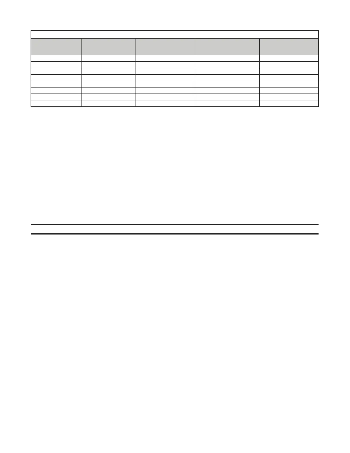
• Refer to Table 15 for option AG40 pressure requirements and to Figure 15 for troubleshooting option AG40.
• This uniquely-designed modulation system requires combustion air pressure settings different from the standard
system. Refer to Table 14 for the approximate combustion air proving switch settings at sea-level operation.
Table 15. Options AG39 and AG40 Pressure Requirements
Unit
Size
Maximum Turndown
(%)
Input Range
(MBH)
Factory-Set Inlet Pressure
to Modulating Valve
(IN WC)
Required
Gas Supply Pressure
(IN WC)
125 20 25–125 3.9 5.0
150 27 40.3–150 3.7 5.0
175 23 40.3–175 3.7 5.0
200 26 51.8–200 3.9 5.0
225 23 51.8–225 3.9 5.0
250 28 69–250 4.0 5.0
300 23 36–300 4.0 5.0
400 25 100–400 4.4 6.0