6
RPB-IOM (06-22) 131782-B
GENERAL INFORMATION—CONTINUED
Dimensions—Continued
Location
⚠ CAUTION ⚠
Do not locate the heater where it may be exposed to water spray, rain, or dripping water.
• Select a location that complies with the requirements in this manual.
• There are a variety of factors, such as system application, building structure, dimensions, and weight, that contribute
to selecting the location.
• The location must comply with the clearances listed in Table 4.
• If the unit is equipped with an outside air hood, it is recommended that the inlet to the hood not be facing into the
prevailing wind.
Weights
Before installation, check the supporting structure to ensure that it has sufficient load-carrying capacity to support
the weight of the unit. Refer to Table 3, which lists unit weight based on unit size.
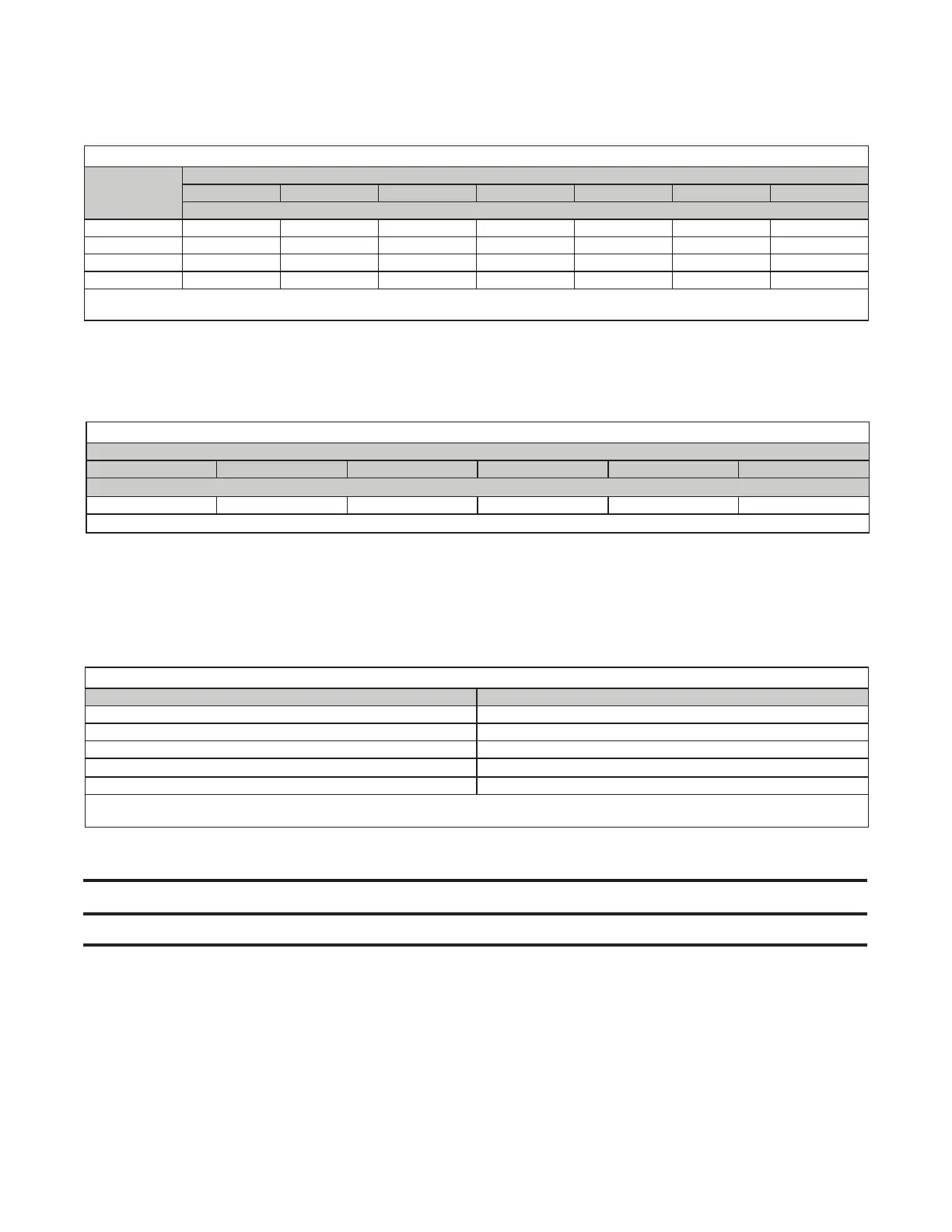
Table 2. Dimensions
Dimension
(See Figure 1)
Unit Size
125 150, 175 200, 225 250 300 350 400
Inches (mm)
A 28-5/8 (727) 34-1/8 (867) 39-5/8 (1006) 47-7/8 (1216) 47-7/8 (1216) 53-3/8 (1362) 58-7/8 (1470)
B 17-3/8 (441) 22-7/8 (581) 28-3/8 (721) 36-5/8 (930) 36-5/8 (930) 42-1/8 (1070) 47-5/8 (1210)
C 25-7/8 (657) 31-3/8 (797) 36-7/8 (937) 45-1/8 (1146) 45-1/8 (1146) 50-5/8 (1286) 56-1/8 (1426)
D 15-1/4 (387) 20-3/4 (527) 26-1/4 (667) 34-1/2 (876) 34-1/2 (876) 40 (1016) 45-1/2 (1156)
Air opening dimensions (inches (mm)): standard horizontal air inlet (19-1/2 (495) × B), optional return air (bottom) (19-1/2 (495) × B),
standard horizontal discharge air (18 (457) × D), and optional vertical discharge air with option AQ5 or AQ8 plenum (19-1/2 (495) × B).
Clearances
Clearance to combustibles is defined as the minimum distance—from the heater to a surface or object—that is
necessary to ensure that a surface temperature of 90°F (50°C) above the surrounding ambient temperature is not
exceeded. For safety, adequate combustion air, and convenient installation and service, ensure that the clearances
listed in Table 4 are provided.
Table 3. Weights
Unit Size
125 150, 175 200, 225 250, 300 350 400
Net Weight (Pounds (kg))*
482 (219) 520 (236) 534 (242) 588 (267) 630 (286) 662 (300)
*Blower and furnace section only.
Table 4. Clearances
Unit Surface Minimum Clearances (Inches (mm))
Top 36 (915)
Control side 6 (152) + width of furnace
Side opposite controls 6 (152)
Bottom, to combustibles
0 (0)*
Bottom, to noncombustibles 0 (0)
*When the unit is installed on a roof curb on a combustible roof, the roof area enclosed within the curb must be either ventilated, left open, or
covered with noncombustible material that has an R-value of at least 5.0.