16
RPB-IOM (06-22) 131782-B
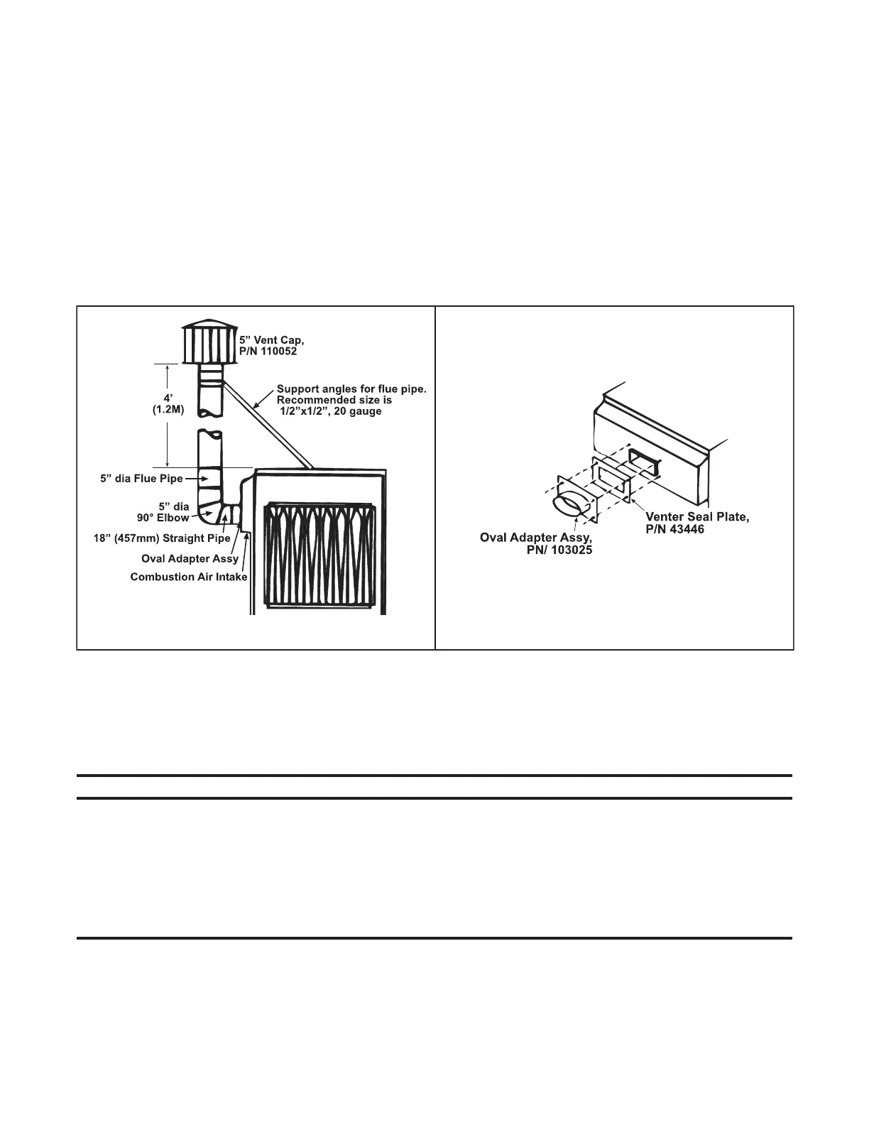
Figure 7. Optional Vertical Flue Discharge
Piping Connections
Gas Supply Pressure
The unit is equipped for a maximum gas supply pressure of 1/2 psi, 3.5 kPa, or 14 IN WC.
NOTES:
Supply pressure higher than 1/2 psi requires the installation of an additional service regulator
external to the unit.
PRESSURE TESTING SUPPLY PIPING
• Test pressures above 1/2 psi—disconnect the heater and manual valve from the gas supply line
to be tested. Cap or plug the supply line.
• Test pressures below 1/2 psi—before testing, close the manual valve on the heater.
DETAIL BDETAIL A
INSTALLATION—CONTINUED
Venting Connections
• Locate power-vented furnaces so that flue discharge is not directed at fresh air inlets. The flue discharge openings
are located on the side of the furnace just above the control access panel. The position of this opening discourages
recirculation of combustion products and provides for furnace operation in all normal weather conditions.
• Optional vertical flue discharge (option CC3): These power vented furnaces are certified with 4 feet of vertical
pipe connected as shown in Figure 7, DETAIL A. The distance is measured from the top of the unit to the bottom
of the vent cap. The vent pipe and supports are field-supplied. Optional vertical vent piping provides compliance
with local codes that require either 10-foot horizontal or 4-foot vertical clearance between the flue outlet and the
fresh air intake of the heating system and/or building. The option package (PN 45021) includes the 5-inch vent
cap, the adapter assembly, and the seal plate as shown in Figure 7, DETAIL B. Attach venter seal plate and oval
adapter assembly with sheet metal screws. Use venter seal plate as drill template.