15
RPB-IOM (06-22) 131782-B
2. Determine orientation of sensor:
a. In horizontal ductwork, position sensor in top-middle of duct with sensor probe extending vertically down into
center of air stream.
b. In vertical ductwork, position sensor in middle of duct that corresponds with top-middle of discharge outlet.
3. Secure sensor in ductwork:
a. For units with option AG3, sensor is factory-installed.
b. For units with option AG8, AG9, AG15, or AG39:
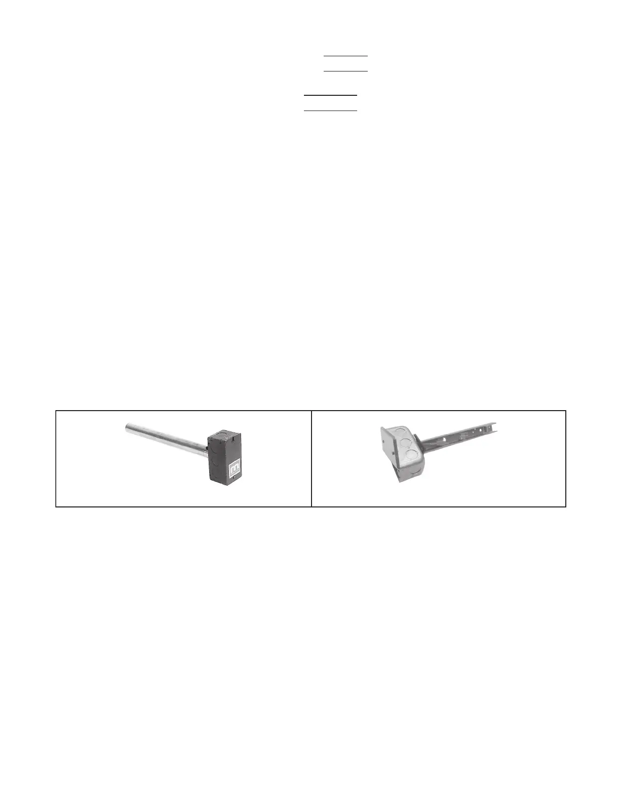
(1) Position of sensor in duct is also important—mixing tube shown in Figure 6, DETAIL A is 12 inches (305
mm) long and holder shown in Figure 6, DETAIL B extends 9-3/16 inches (233 mm) into ductwork.
(2) Turn holder so that element is shielded from direct airflow and will sense air temperature as it flows through
holes in holder.
(3) At selected ductwork location, mark diamond-shaped hole—approximately 1 × 1 inch (25 × 25 mm—
required for sensor holder or round hole required for mixing tube and cut hole no larger than necessary.
(4) For units with option AG8, AG9 or AG39, slide mixing tube (see Figure 6, DETAIL A) into ductwork and
attach sensor.
(5) For units with AG15, push element into clip in holder (see Figure 6, DETAIL B), slide holder into ductwork,
and position holder so that it shields sensor from direct airflow. Secure box portion of holder to ductwork
using four field-supplied #6 sheet metal screws.
c. For units with option AG40, install field-supplied sensor in accordance with instructions provided with sensor.
5 ×
�
4 × 12 × 24
3.14
= 96 ℎ
5 ×
�
4 × 305 × 610
Figure 6. Discharge Air Temperature Sensor and Holder
4. Connect sensor wires:
a. For units with option AG15:
(1) Determine where sensor wire should enter box and remove knockout.
(2) Secure field-supplied cable connector to box, connect sensor wire, and install box cover.
b. For all options, ensure that all sensor wires are connected in accordance with wiring diagram provided with unit.
DETAIL A: OPTIONS AG8, AG9, AND AG39
DETAIL B: OPTION AG15