21
RPB-IOM (06-22) 131782-B
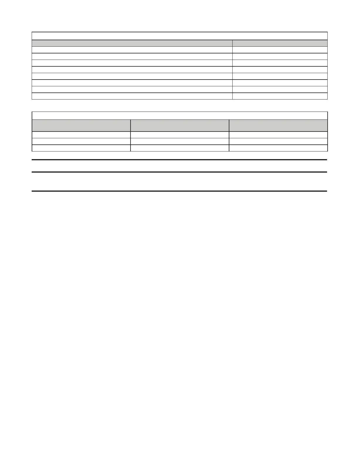
Table 12. Amp Ratings of 24V Optional Controls
Control Ampere Rating (Maximum Amps)
Fan control 0.12
Time delay relay heater 0.10
Relay coil 0.12
Motor contactor coil 0.33
Spark ignition system 0.10
Maxitrol gas control system 0.50
Single-stage gas valve 0.60
Two-stage gas valve 0.60
Table 13. Control Wiring Sizes
Distance from Unit to Control
(Feet (Meters))
Minimum Recommended Wire Gauge
(AWG)
Total Wire Length
(Feet (Meters))
75 (23) #18 150 (46)
125 (38) #16 250 (76)
175 (53) #14 350 (107)
⚠ CAUTION ⚠
Ensure that the thermostat has an adequate VA rating for the total requirements. Add the coil rating
of all relays and match the thermostat rating.
• Thermostat: A 24V thermostat must be used to actuate low voltage gas controls. If line voltage from the thermostat
to the unit is desired, consult the factory representative. Thermostats should be located 5 feet (1.5 meters)
above the floor on an inside wall, not in the path of warm or cold air currents and not in corners where air may
be pocketed. Do NOT install on cold air walls. For specific connection details, refer to instruction packet with the
thermostat. If more than one unit is cycled from one thermostat, separately activated relays must be substituted
at unit thermostat connections.
• Remote console: If the unit being installed includes an optional remote console, it is shipped separately for field
installation. All consoles include indicator lights for the blower and burner. Consoles may include a dirty filter
indicator light, a cooling indicator light, an ON/OFF switch, a summer/off/winter switch, a heat/vent/cool switch, a
potentiometer, a thermostat, and/or a Maxitrol temperature selector. Consoles are shipped separately for remote
installation and may be either mounted on a wall or recessed.
• Maxitrol system: Control wires connected to a Selectrastat, a discharge air sensor, a remote temperature selector
or sensor, an amplifier, or the valve must not be run close to or inside conduit with power or ignition wires. Doing
so may cause the unit to function erratically or may destroy the amplifier. If shielded wires are used, shield must
be insulated and grounded at the amplifier location only.
• Pressure null switch:
a. Select indoor location free from excessive vibration where oil or water will not drip onto switch and where
ambient temperature is −30°F (dry air) to 110°F.
b. Mount switch with diaphragm in vertical plane. Switch is position-sensitive and is calibrated to operate properly
when diaphragm is vertical. Mount switch securely.
c. Connect pressure taps on top of switch to sources of air pressure differential. Metal tubing with 1/4-inch OD is
recommended, but any tubing system that does not unduly restrict air flow may be used. To maintain positive
building pressure, vent low pressure tap to outdoors and allow high pressure tap to monitor building pressure.
To maintain negative building pressure, reverse functions of high and low pressure taps. In either case, ensure
that outdoor vent is protected from wind and is screened from insects.
d. Adjustment of switch: HIGH actuation point of switch is indicated on calibrated scale secured to transparent
range screw enclosure. Building pressure is set by turning adjustment screw. LOW actuation point is set by
adjusting span of null by turning span adjustment screw. Span range is 0.01 to 0.03 IN WC.
e. Refer to wiring diagram provided with unit to make electrical connections.