Calibration
CGS-240 Manual 6/15/2021
Page 52 of 148
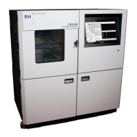
3) Insert the Sat temperature probe into the cavity and through the
Swagelok nut from which It had been previously removed. Insert
it so that only 1/8” to 1/4” of the probe’s metal sheath remains
visible.
4) Tighten the nut using the deep access T-wrench.
The T-wrench prevents overtightening.
5) Wrap the foam insulating plug over the cable and push into the cavity.
6) Place the round plastic plug over the cable and insert it fully to cap the hole.
7) Coil any excess cable and reattach at the clamp near the front of the saturator box,
where it was previously removed.
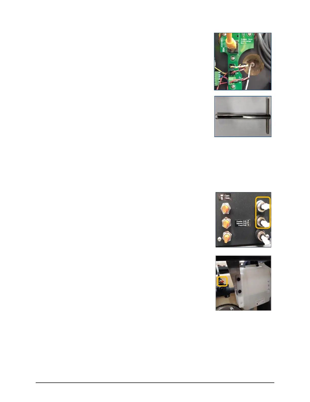
8) Ensure the saturator and chamber drains are closed, then remove
the tubes and reinsert the 1/4” drain plugs.
9) Pour the previously drained fluid back into the fluid tank (located
behind the chamber).
10) After running the system for several minutes, be sure to close the
vent valve located behind the chamber (top, center) near the
tank.
With the vent valve open, air can more easily escape from the
system. However, an open vent valve causes the water tank to
heat and cool with the chamber and saturator. The system
operates more efficiently with a closed vent valve, which then
provides some isolation of the tank from the chamber and
saturator temperatures.
 Loading...