requires cooling, the ECB’s DC CONTROL – RLY 7 sources 24 VDC to the sat cool solenoid, causing it to open and
inject refrigerant. An LED at RLY 7 also indicates the relay status. When the LED is ON, the valve is energized. The
refrigeration compressor temperature is measured by temperature probe, T
R
.
6.5 HEATERS
The humidity generator requires several different heating zones to properly create and maintain humidity without
fear of adverse condensation. Heating is required in the presaturator, circulating fluids, and expansion valve.
6.5.1 PRESATURATOR HEATER, H1
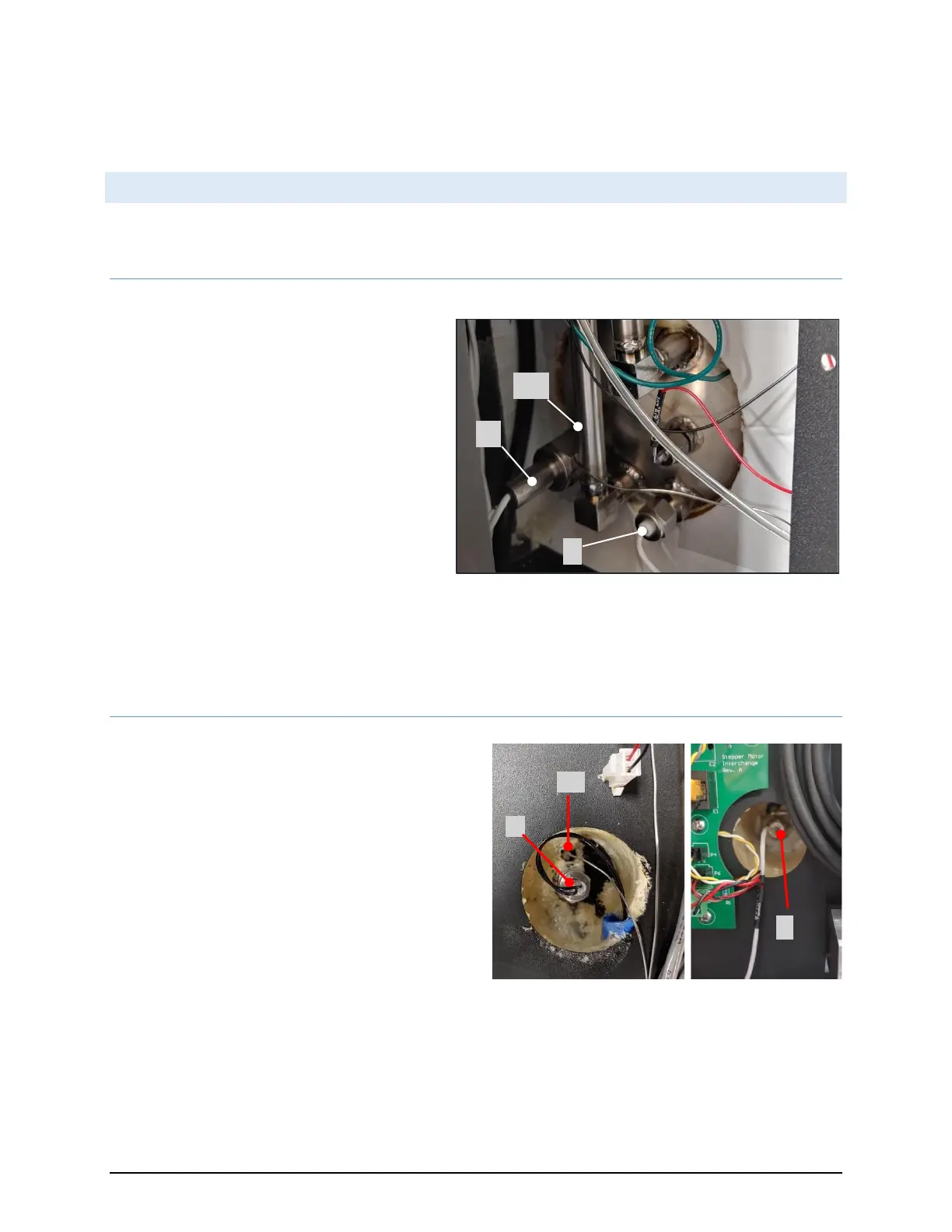
The presaturator warms the incoming gas to
oversaturate it with water vapor. This is
accomplished through heating of the presat water.
A 1500-watt stainless steel insulated immersion
heater provides this function. The presat water is
warmed to and maintained at setpoint through
pulse width modulation of the heater using
feedback from the presat temperature sensor, Tp.
When heating is required, the ECB’s AC CONTROL –
A1 digital output activates solid state relay SSR3
which completes the AC current path through
circuit breaker CB3 to the presaturator heater. A1’s
digital output is visually indicated with an adjacent LED.
The heater ON status is also indicated with an LED on the solid-state relay SSR2. AC power to the heater is also
protected by a thermal cutout switch, TH1, which removes AC power in the event of over temperature. The presat
temperature is measured by temperature probe, T
P
.
6.5.2 SATURATOR FLUID HEATER, H2
The saturator temperature is maintained by heating or
cooling the circulating fluid as needed. Heating is
accomplished by activating a 500-watt stainless steel
insulated immersion heater, H2, inserted in the
circulating fluid. The circulating fluid temperature is
warmed to and maintained at setpoint through pulse
width modulation of the fluid heater using feedback from
the saturator temperature sensor, T
S
. When heating is
required, the ECB’s AC CONTROL – A2 digital output
activates solid state relay SSR3 which completes the AC
current path through circuit breaker, CB4, to the fluid
heater.
A2’s digital output is visually indicated with an adjacent LED. The heater ON status is also indicated with an LED on
the SSR3. AC power to the heater is also protected by a thermal cutout switch, TH2, which removes AC power in
the event of over temperature.


 To Next Page