Subsystems
CGS-240 Manual 6/15/2021
Page 75 of 148
6.7 TEMPERATURE MEASUREMENTS
The Precision Temperature Measurement board is a multi-channel, 24-bit, A/D converter system used to measure
all temperatures in the humidity generator. It connects to the ECB either of its RS-232 port. While two of the A/D
converter channels are configured for reference resistor measurements, the remaining channels are configured for
connection of 100Ω platinum resistance thermometers (PRTs). The following table lists the probe channels and
functions of the humidity generator.
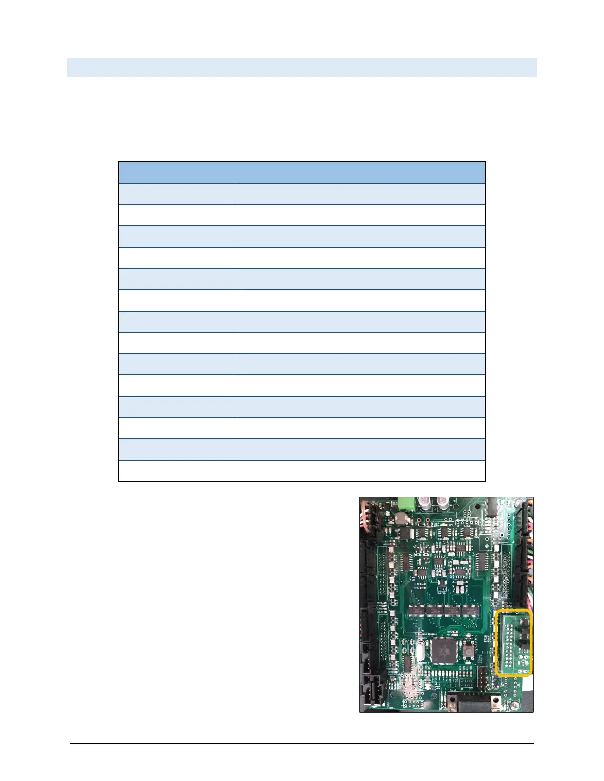
All probes are wired to the temperature board as 4-wire, 100Ω PRTs.
All probe connections are made via straight single row, 6-pin Molex
plugs. The reference resistor pack houses two individual reference
resistors (R
60
and R
140
) and connects via a dual row header. The
reference resistors are known stable resistances, whose values are
programmed into the reference resistor pack. These resistors are
measured and their known values are queried and used in
determination of all PRT resistances. Since the reference resistor
pack is constructed with memory chips, the temperature
measurement board accepts any reference values mounted to any of
channels 13-16. The system requires a minimum of 2 reference
resistors but can utilize up to 4 references resistors if present. The
Precision Resistance Measurement board communicates via RS-232
to the ECB UART 7.
 Loading...