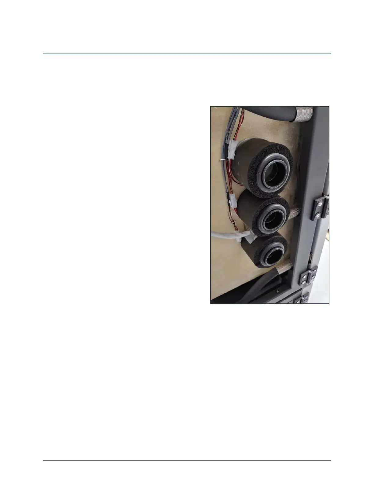
6.5.5 ACCESS PORT HEATERS
The system has three access ports on the left side of the chamber. Figure 6.33 shows the three ports, as seen when
the side panel is removed.
To prevent condensation during high temp/high humidity
generation, each port is equipped with independent
temperature measurement and control. The ports are heated
and maintained at desired temperature through pulse width
modulation of their respective relays, using feedback from their
associated temperature sensors.
The upper access port temperature, T
PU
, is measured on
temperature channel T10. A low-wattage heater, H7, is
connected to RLY 16. Heating is accomplished by activating the
ECB’s DC CONTROL – RLY 16 to source 24 VDC to the heaters.
RLY 16’s output is visually indicated with an adjacent LED. When
the LED is ON, the heater is active.
The center access port temperature, T
PC
, is measured on
temperature channel T11, A low-wattage heater, H8, is
connected to RLY 17. Heating is accomplished by activating the
ECB’s DC CONTROL – RLY 17 to source 24 VDC to the heaters.
RLY 17’s output is visually indicated by an adjacent LED. When
the LED is ON, the heater is active.
The lower access port temperature, T
PL
, is measured on
temperature channel T12. A low-wattage heater, H9, is
connected to RLY 18. Heating is accomplished by activating the
ECB’s DC CONTROL – RLY 19 to source 24 VDC to the heaters.
RLY 19’s output is visually indicated with an adjacent LED. When
the LED is ON, the heater is active.