Subsystems
CGS-240 Manual 6/15/2021
Page 53 of 148
SUBSYSTEMS
This section provides details of the functional systems within the humidity generator. These subsystems include
the Electrical System, Pneumatic System, Fluid System, Refrigeration System, and Heaters.
6.1 ELECTRICAL SYSTEM
The humidity generator requires 200-240 VAC, 50/60 Hz, single phase power. Configuration for the AC input can be
either
• LINE1, LINE2, GND (as is often the case for connection in the U.S., Canada, Mexico, Japan and Taiwan
where LINE1 and LINE2 are of opposing phase while each is approximately 100-120 VAC with respect to
GND), resulting in 200-240 VAC between Line 1 & Line 2;
• LINE, NEUTRAL, GND (often for Europe and many countries of Asia when LINE is approximately 200-240
VAC with respect to NEUTRAL, with NEUTRAL and GND at the same potential.)
AC power enters the system via the power connector located at the back panel, transferring AC into the system via
a 2 pole, 15 AMP circuit breaker switch. When this switch is turned on, AC power is also applied to the input of a 2-
pole mechanical circuit breaker inside the system behind the right door at the main control panel. This circuit
breaker, CB8, is labeled “Main Power.”
Traveling through the circuit breaker, power is then branched to several locations. AC power is applied to a 5V
power supply. Line 1 and line 2 power are also applied to solid-state relays, one for each power phase. These two
solid-state relays, SSR7 and SSR8, act as master control to enable or disable heating and refrigeration, compressor
and fan, and all other AC activated components in the system. AC power is also applied to solid-state relay, SSR6,
which controls a 24V DC power supply for powering the internal embedded computer, and a 12V DC power supply,
which runs the user interface PC.
6.1.1 DC POWER SUPPLIES
There are 3 independent DC power supplies in the system, each operating various functions.
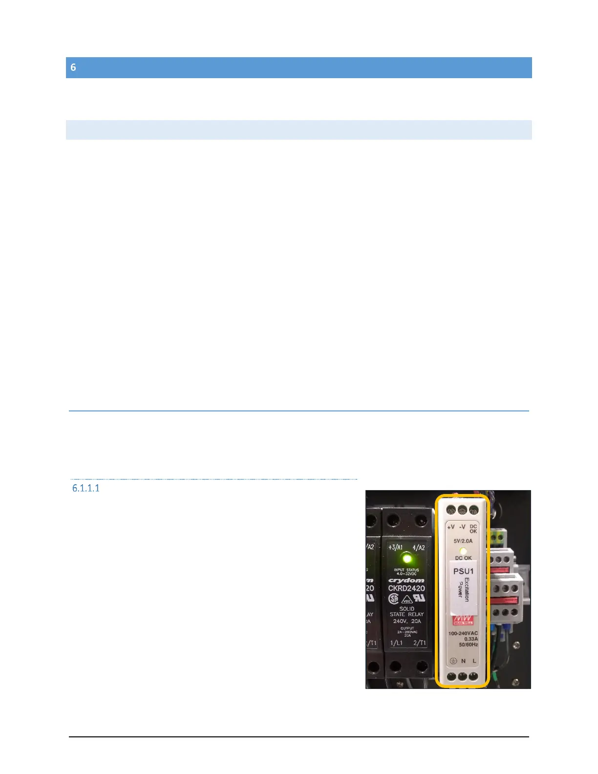
5V DC POWER SUPPLY
A small 5V DC power supply, PSU1, provides excitation power only to
operate a few solid-state relays. The 5V DC power is applied through
the main front panel power switch mounted below the computer
monitor. When the power switch is pressed, this 5V DC applies an
enable signal to the two master control solid-state relays, SSR7 and
SSR8, mentioned in the previous section. These two solid-state relays
apply power to the bank of AC Circuit breakers on the lower portion of
the control panel.
When the main power switch is on, the 5V DC is also supplied through a
diode, D2, to the solid-state relay, SSR6, which energizes the 12V and
24V power supplies.
 Loading...