Subsystems
CGS-240 Manual 6/15/2021
Page 56 of 148
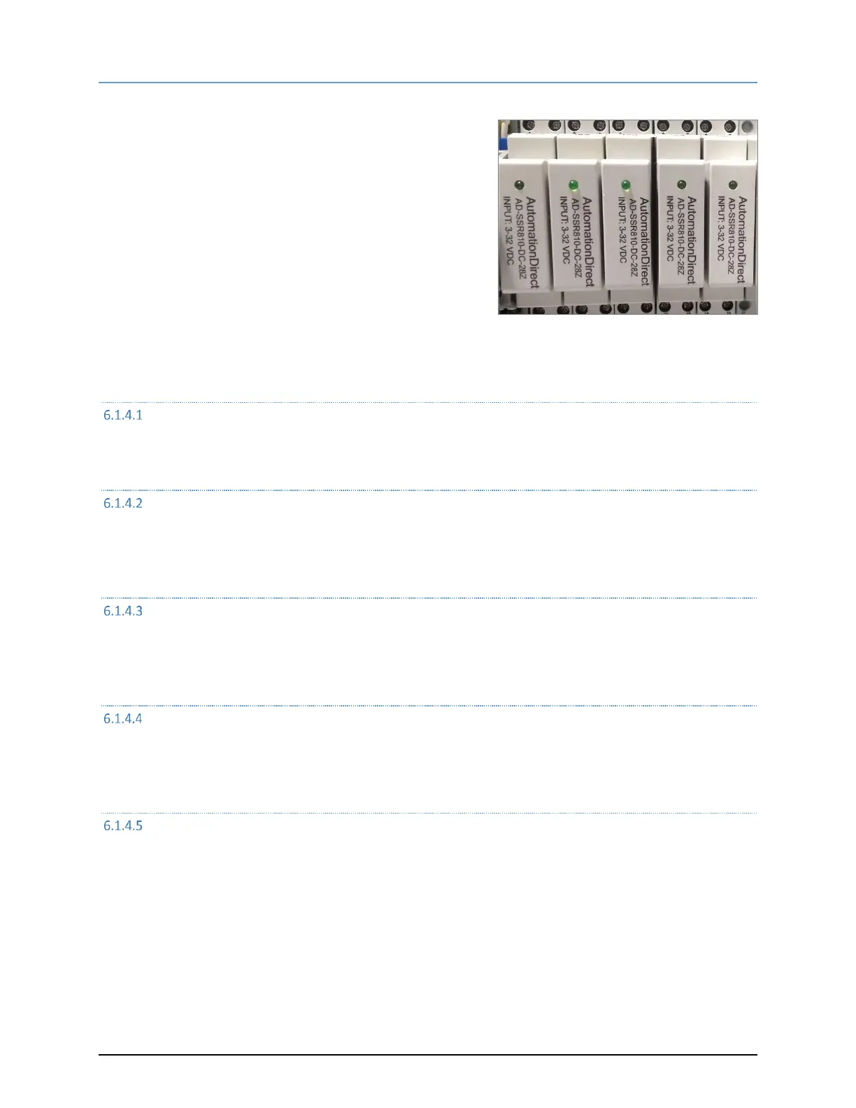
6.1.4 SOLID-STATE AC POWER RELAYS
There are 5 solid-state relays labeled SSR1-SSR5 connected to the
main controller board. The main controller board provides them
with the 5V control signals. The AC side of these solid-state relays
are connected to the various components and provide AC power to
those components when activated and when their associated
circuit breakers are turned on.
R134A COMPRESSOR POWER
SSR1 is activated by output A0 of the ECB main controller board. When activated, AC power is applied from circuit
breaker, CB2, through SSR1 to the refrigeration compressor.
PRE-SATURATOR HEAT
SSR2 is powered by output A1 of the ECB main controller board. When activated, SSR2 applies AC power through
circuit breaker, CB3, to the pre-sat heater. The amount of heat applied is controlled by pulse with modulation of
that output A1 on the main controller board.
SATURATOR HEAT
SSR3 is activated by output A2 of the ECB main controller board. When activated, AC power is applied through
SSR3 and circuit breaker, CB4, to the Sat Heater. Control of heat is regulated by the pulse with output from main
controller board output A2.
CHAMBER HEAT
SSR4 is activated by output A3 of the ECB main controller board. When activated, AC power is applied to the
chamber heater through SSR4 and circuit breaker, CB5, to power the heater. Control of heater power is maintained
by pulse width modulation of the main controller boards output A3.
CHAMBER FAN
Output A4 of the ECB main controller board activates SSR5. When activated, AC power is applied through SSR5 and
circuit breaker, CB6, to the chamber fan activating the fan. The fan is generally on or off and is not speed
controlled.
 Loading...