20
CONTENTS
Italiano pag. 4
English
page 20
Français page 36
Deutsch Seite 52
Español pág 68
I SECTION I: USER..................................................................................21
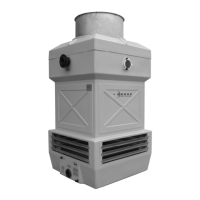
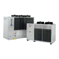
I.1 Available versions.....................................................................................................21
I.2 Machine identification ..............................................................................................21
I.3 Specified conditions of use......................................................................................21
I.4 Operating limits.........................................................................................................21
I.5 Warnings regarding potentially toxic substances .................................................22
I.6 Information on residual risks and irremovable hazards........................................22
I.7 Description of controls.............................................................................................23
I.7.1 Mains switch................................................................................................................23
I.7.2 Automatic switches .....................................................................................................23
I.7.3 Control keypad installed on machine ..........................................................................23
I.8 Instructions for use...................................................................................................23
I.8.1 Unit power supply........................................................................................................24
I.8.2 Isolation from the electricity network ...........................................................................24
I.8.3 Start-up .......................................................................................................................24
I.8.4 Switching off................................................................................................................24
I.8.5 Changing the operating mode (THCE only) ................................................................24
I.8.6 Keypad-modifiable regulation variables ......................................................................25
I.8.7 Setting summer and winter set-points.........................................................................25
I.9 Menu navigation........................................................................................................26
I.9.1 LED status signals ......................................................................................................27
I.9.2 Alarm signals...............................................................................................................27
II SECTION II: INSTALLATION AND MAINTENANCE.............................28
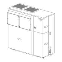
II.1 Unit description.........................................................................................................28
II.1.1 Construction features..................................................................................................28
II.1.2 Electric panel...............................................................................................................28
II.2 Spare parts and accessories....................................................................................28
II.3 Transport - handling - storage .................................................................................29
II.3.1 Packaging, components..............................................................................................29
II.4 Handling instructions ...............................................................................................29
II.4.1 Storage conditions ......................................................................................................30
II.5 Installation instructions............................................................................................30
II.5.1 Installation site requirements.......................................................................................30
II.5.2 Indoor installation........................................................................................................30
II.5.3 Clearance spaces, positioningand ducting..................................................................31
II.6 Water connections....................................................................................................31
II.7 Electrical connections ..............................................................................................32
II.8 Start-up instructions.................................................................................................32
II.8.1 Configuration...............................................................................................................33
II.8.2 Unit start-up.................................................................................................................33
II.8.3 Periods out of use .......................................................................................................33
II.8.4 Starting up again after long periods of inactivity..........................................................33
II.9 Nature and frequency of scheduled inspections ...................................................33
II.10 Maintenance instructions.........................................................................................34
II.10.1 Ordinary maintenance.................................................................................................34
II.10.2 Special maintenance...................................................................................................34
II.11 Instructions for dismantling the unit and disposing of hazardous substances..34
II.12 Check-list...................................................................................................................35
ENCLOSED DOCUMENTS
A1 Part Identification…………………………………………………………..........….....89
A2 Technical data…………………………………………………………....…………....90
A3 Dimensions ….……………………………………………………………..................91
A4 Water Connections….….……………………………………………………………..93
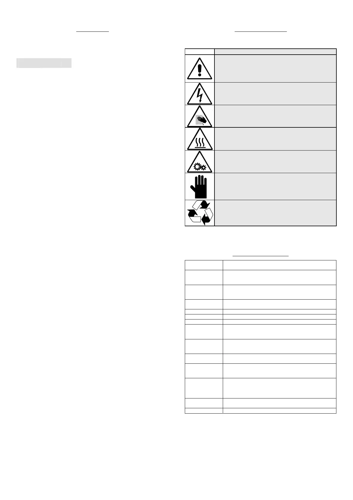
KEY TO SYMBOLS
SYMBOL
MEANING
GENERIC DANGER!
The GENERIC DANGER sign warns the operator
and maintenance personnel about risks that may
cause death, physical injury, or immediate or latent
illnesses of any kind.
DANGER: LIVE COMPONENTS!
The DANGER: LIVE COMPONENTS sign warns the
operator and maintenance personnel about risks
due to the presence of live voltage.
DANGER: SHARP EDGES!
The DANGER: SHARP EDGES sign warns the
operator and maintenance personnel about the
presence of potentially dangerous sharp edges.
DANGER: HOT SURFACES!
The DANGER: HOT SURFACES sign warns the
operator and maintenance personnel about the
presence of potentially dangerous hot surfaces.
DANGER: MOVING PARTS!
The DANGER: MOVING PARTS sign warns the
operator and maintenance personnel about risks
due to the presence of moving parts.
IMPORTANT WARNING!
The IMPORTANT WARNING sign draws attention to
actions or hazards that could damage the unit or its
equipment.
ENVIRONMENTAL PROTECTION!
The ENVIRONMENTAL PROTECTION sign provides
instructions for using the machine in an eco-
friendly fashion.
Reference Standards
UNI EN 292
Sicurezza del macchinario. Concetti fondamentali, principi
generali di progettazione.
UNI EN 294
Sicurezza del macchinario. Distanze di sicurezza per
impedire il raggiungimento di zone pericolose con gli arti
superiori.
UNI EN 563
Sicurezza del macchinario. Temperature delle superfici di
contatto. Dati ergonomici per stabilire i valori limiti di
temperatura per superfici calde.
UNI EN 1050
Sicurezza del macchinario. Principi per la valutazione del
rischio.
UNI 10893
Documentazione tecnica di prodotto. Istruzioni per l’uso.
EN 13133
Brazing. Brazer approval.
EN 12797
Brazing. Destructive tests of brazed joints.
EN 378-1
Refrigeration systems and heat pumps – safety and
environmental requirements. Basic requirements,
definitions, classification and selection criteria.
PrEN 378-2
Refrigeration systems and heat pumps – safety and
environmental requirements. Design, construction, testing,
installing, marking and documentation.
CEI EN 60204-1
Sicurezza del macchinario. Equipaggiamento elettrico delle
macchine. Parte 1: Regole generali.
CEI EN 60335-2-40
Sicurezza degli apparecchi elettrici d’uso domestico e
similare. Parte 2: norme particolari per le pompe di calore
elettriche, per i condizionatori d’aria e per i deumidificatori.
UNI EN ISO 3744
Determinazione dei livelli di potenza sonora delle sorgenti
di rumore mediante pressione sonora. Metodo tecnico
progettuale in un campo essenzialmente libero su un piano
riflettente
.
EN 50081-1:1992
Electromagnetic compatibility - Generic emission standard
Part 1: Residential, commercial and light industry.
EN 61000
Electromagnetic compatibility (EMC).
 Loading...