ENCLOSED DOCUMENTS
90
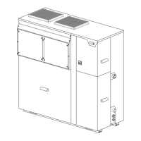
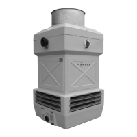
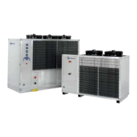
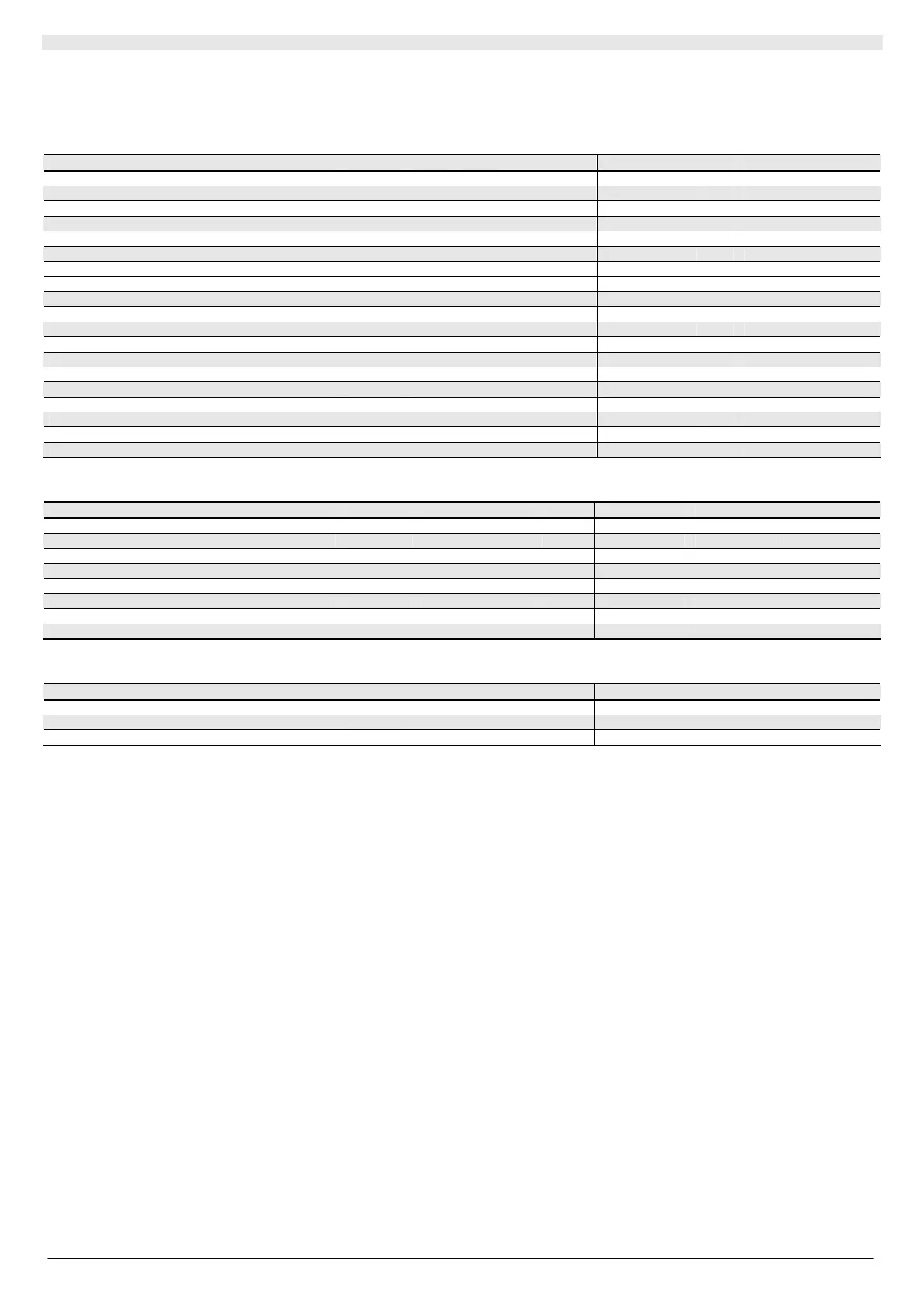
A2 TECHNICAL DATA
TCCE - THCE 114 117 121 126 114 T 114 H 117 T 117 H 121 T 126 T
Nominal cooling capacity (*) kW 14,1 16,6 21,2 25,4 14,1 14,1 16,6 16,6 21,2 25,4
E.E.R. 2,47 2,60 2,65 2,61 2,47 2,47 2,60 2,60 2,65 2,61
Nominal heating capacity (**) kW 14,3 17,3 21,5 25,6 15,3 15,3 18,7 18,7 23,2 28,3
C.O.P. 2,51 2,73 2,78 2,77 3,16 3,16 3,39 3,39 3,34 3,37
Sound pressure (***) dB(A) 54 55 56 57 54 54 55 55 56 57
Scroll compressor No. 1 1 1 1 1 1 1 1 1 1
Fans 2x kW 0,56 0,56 0,56 0,56 0,56 0,56 0,56 0,56 0,56 0,56
Fan E.S.P. Pa 90 80 90 80 90 90 80 80 90 80
Water side exchanger nominal water flow (*) l/h 2417 2871 3637 4365 2427 2427 2871 2871 3637 4365
Exchanger water contents l 1,50 1,70 1,90 2,40 1,50 1,50 1,70 1,70 1,90 2,40
Nominal pressure drops, water side exchanger (*) kPa 17 17 22 16 - - - - - -
Pump external static pressure (*) kPa - - - - 47 174 41 154 151 139
Storage tank water content l - - - - 55 55 55 55 80 80
R407C refrigerant charge ● kg see serial number plate see serial number plate
R407C refrigerant charge (THCE) ● kg see serial number plate see serial number plate
Polyester oil charge ▲ kg 1,90 1,60 3,15 3,15 1,90 1,90 1,60 1,60 3,15 3,15
Polyester oil charge (THCE) ▲ kg 1,90 1,60 3,15 3,15 1,90 1,90 1,60 1,60 3,15 3,15
TCCE weight kg 250 270 330 360 340 340 360 360 420 460
THCE weight kg 270 280 350 370 350 350 370 370 440 440
Electrical data 114 117 121 126 114 T 114H 117 T 117 H 121 T 126 T
Total absorbed power (summer operation) (*) kW 5,70 6,43 7,99 9,73 5,89 6,35 6,62 7,08 8,64 10,38
Total absorbed power (winter operation) (**)
kW 5,70 6,43 7,99 9,73 5,85 6,31 6,52 6,98 8,41 9,85
Electrical power supply V-ph-Hz 400-3-50 400-3-50
Auxiliary power supply V-ph-Hz 230-1-50 230-1-50
Nominal current (summer operation) A 13,4 14,1 16,7 19,3 14,2 16,4 15,0 17,2 19,8 22,3
Nominal current (winter operation) A 13,6 14,5 17,1 19,7 14,4 16,6 15,3 17,5 20,1 22,7
Max. current A 15,0 16,6 19,3 22,3 15,9 18,1 17,5 19,7 22,3 25,3
Starting current A 66 74 98 130 66 66 74 74 98 130
Water connections 114 117 121 126 114 T 114H 117 T 117 H 121 T 126 T
Water inlet/outlet
Ø
1 ½”G (male) 1 ½”G (male)
Condensation drain (THCE only)
Ø
30 mm 30 mm
Storage tank train (T versions only)
Ø
- ½”G (Female)
(*) In the following conditions: condenser input air temperature 35°C; chilled water temperature 7°C; temperature differential at evaporator
5°C.
(**) In the following conditions: evaporator input air temperature 6°C W.B.; hot water temperature 45°C; temperature differential at evaporator
5°C.
(***)Sound pressure level in dB(A) measured at a distance of 5 m from the unit, with directionality factor of 2 and ducting on the fan outlet.
● Check the serial number plate attached to the machine.
▲ Check the plate attached to the compressor.
N.B. The C.O.P. and EER calculation do not take the electric power absorbed by the circulating pump into account.
 Loading...