EasyManuals Logo

RHOSS MICROSYSTEM TCCE 114 Series User Manual

RHOSS MICROSYSTEM TCCE 114 Series
Go to English
112 pages
To Next Page IconTo Next Page
To Previous Page IconTo Previous Page
Page #89 background imageLoading...
Page #89 background image
ENCLOSED DOCUMENTS
89
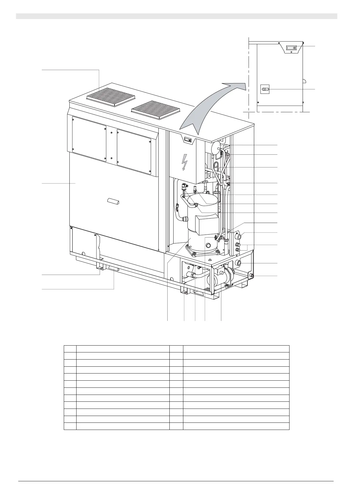
A1 PART IDENTIFICATION (SPECIFIC TO THCE)
1
2
3
4
5
6
7
8
9
11
12
13
14
15
1617
18
19
20
21
23
22
10
Key:
1 Control board 13 Water inlet
2 Main switch 14 Discharge
3 Liquid receiver 15 Circulation pump
4 Winter thermostatic expansion valve 16 Summer thermostatic expansion valve
5 4-way valve 17 Safety valve
6 Air bleed cock 18 Tank
7 Drier filter 19 Scroll compressor
8 Bleed valve 20 Lifting sling slots
9 Safety pressure switch 21 Unit floor-fixture slots
10 Water drain 22 Inspection panel
11 Water outlet 23 Fan outlet mouths
12 Supply and control cable inlet

Table of Contents

Questions and Answers:

Question and Answer IconNeed help?

Do you have a question about the RHOSS MICROSYSTEM TCCE 114 Series and is the answer not in the manual?

RHOSS MICROSYSTEM TCCE 114 Series Specifications

General IconGeneral
BrandRHOSS
ModelMICROSYSTEM TCCE 114 Series
CategoryChiller
LanguageEnglish

Related product manuals