ELECTRICAL COMPONENT DESCRIPTIONS
SM 1-11 A265/A267
Overall
Information
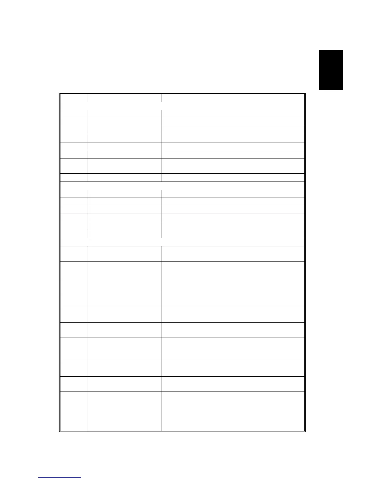
1.5 ELECTRICAL COMPONENT DESCRIPTIONS
Refer to the electrical component layout on the reverse side of the point-to-point
diagram for the location of the components.
Symbol Name Function
Motors
M1 Scanner Drives the 1st and 2nd scanners.
M2 Polygonal Mirror Turns the polygonal mirror.
M3 Main Drives the main unit components.
M4 Exhaust Fan Removes heat from around the fusing unit.
M5 Upper Paper Lift Raises the bottom plate in the 1st paper tray.
M6 Lower Paper Lift Raises the bottom plate in the 2nd paper tray.
M7
Toner Supply Rotates the toner bottle to supply toner to the
development unit.
Magnetic Clutches
MC1 Upper Paper Feed Starts paper feed from the 1st paper tray.
MC2 Lower Paper Feed Starts paper feed from the 2nd paper tray.
MC3 Upper Relay Drives the upper relay rollers.
MC4 Lower Relay Drives the lower relay rollers.
MC4 Registration Drives the registration rollers.
Switches
SW1 Main
Provides power to the machine. If this is off, there
is no power supplied to the machine.
SW2 Right Upper Cover
Detects whether the right upper cover is open or
not.
SW3 Right Cover
Cuts the +5VLD and +24V dc power line and
detects whether the right cover is open or not.
SW4 Right Lower Cover
Detects whether the right lower cover is open or
not.
SW5 Upper Paper Size
Determines what size of paper is in the upper
paper tray.
SW6 Lower Paper Size
Determines what size of paper is in the lower
paper tray.
SW7 Special Paper
Determines whether there is special paper in the
lower paper tray.
SW8 New PCU Detect Detects when a new PCU is installed.
SW9 Front Cover Safety
Cuts the +5VLD and +24V dc power line and
detects whether the front cover is open or not.
SW10 Operation
Provides power for machine operation. The
machine still has power if this switch is off.

 Loading...