32DF9T02.C
2 - 2
CAUTION!
It is important that fasteners used for lift mounting do not protrude into the lift
interior. Fasteners that are too long can interfere with movement of carriage.
c. Threaded fasteners for mounting lift are 5/16-18, and must be grade 5, or higher. Their length
must provide at least 5/16” and no more than 7/16” of thread engagement with threaded inserts.
d. If adjustment slots are added to mounting brackets, they must be horizontal. Horizontal slots,
rather than vertical, will prevent the lift slipping downward if the hardware loosens.
e. Vertical adjustment must be accomplished placing shims between the mounting brackets and
vehicle frame. Maximum shim thickness is 1/8”.
f. Use at least two
mounting points at each corner of enclosure to support lift.
g. The top four corners of the enclosure must be in the same plane, +/- 1/8”. Shim, as required.
h. Mounting brackets must be painted or treated to protect against rust and corrosion.
3. HYDRAULIC POWER UNIT
a. Hydraulic Power Unit Mounting Notes
The hydraulic power unit must be located so that operator has a clear view of platform while
operating manual back-up system.
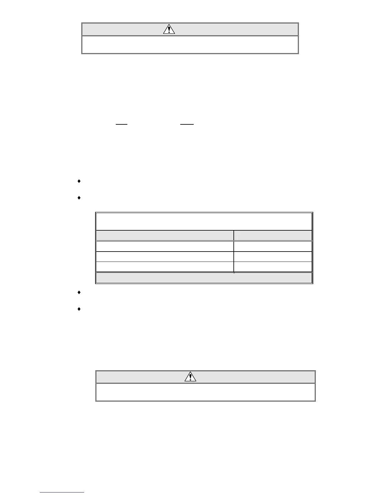
The load capacity of brackets used to mount hydraulic power unit must meet criteria in
Table 2-2:
TABLE 2-2: LOAD CAPACITY REQUIREMENTS FOR HYDRAULIC
POWER UNIT MOUNTING BRACKETS
LOAD DIRECTION BRACKET CAPACITY
Vertical 125 lb
Longitudinal (perpendicular to drive axles) 200 lb
Lateral (parallel to drive axles) 100 lb
END OF TABLE
Meeting these criteria assures that the pump mounting will withstand normal loads occuring
during transit, and also during manual pump use.
Be certain pick-up tube is oriented properly when pump assembly is horizontally mounted.
Also, be certain breather plug oriented properly (requires elbow fitting).
b. Power Unit to Pull Box Connection
1) Connect main hydraulic hose to hydraulic power unit, if not already done.
2) Operate manual backup pump until hydraulic fluid flows out open end of hose.
3) Connect open end of hose to hydraulic fitting located on side of pull-box.
4) Deploy platform and lower to ground.
CAUTION!
Check and add hydraulic fluid when platform is at ground level. Adding fluid
with platform raised will cause oil reservoir to overflow when it is lowered.
5) Remove temporary plug on top of hydraulic pump reservoir. Verify that hydraulic fluid in
reservoir is at FULL level. Add Texaco 01554 Aircraft Hydraulic Oil, or equivalent U.S. mil
spec H5606G fluid, if necessary. Replace temporary plug with supplied breather plug.
6) Refer to Final Adjustments section in this chapter for hydraulic bleeding procedure.
 Loading...