32DF9T02.C
4 - 21
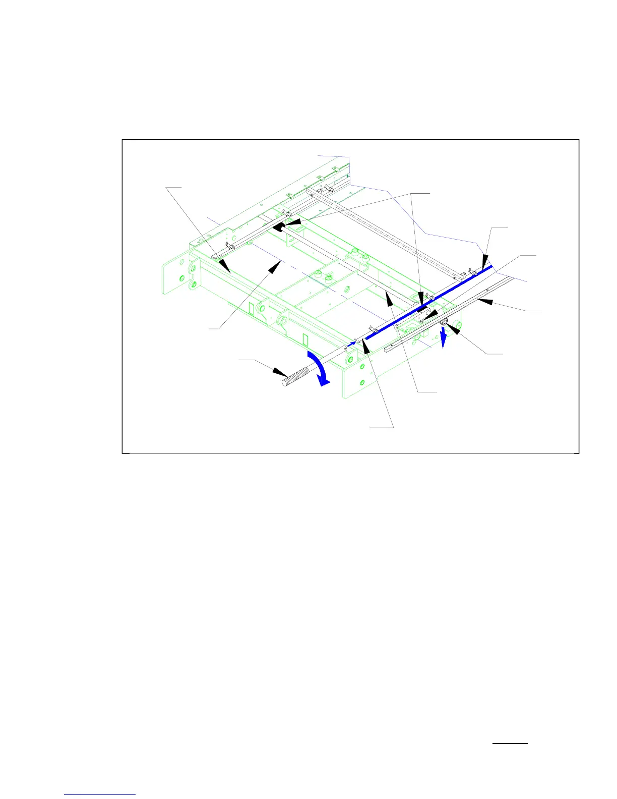
5. MANUAL PLATFORM RELEASE MECHANISM
Refer to Figure 4-20. The travelling frame (carriage, lifting frame, and platform) can be manually dis-
engaged from the enclosure by rotating either platform release shaft. Each release shaft has an ec-
centric cam that bears against a roller on the driveshaft. Rotating a release shaft pushes the final
driveshaft downward (against the force of an engagement spring), disengaging each driveshaft pinion
gear from its gear rack (mounted to the inside of the enclosure). Once the deployment system is dis-
engaged, the travelling frame can be moved by hand. The deployment system will automatically re-
engage when the platform is moved to the opposite end of its travel (stow or deploy).
a. Reset Ramp Adjustment
Rotating a release shaft disengages the platform from the enclosure. The reset ramps re-engage
the deployment system when the platform is moved to the opposite end of its travel. There are
two reset ramps; each one is a small, white plastic block. One ramp re-engages platform when it
is fully deployed, the other when platform is fully stowed. Both ramps are located at the top, rear
of carriage, above the final driveshaft. The adjustment procedure is similar for both ramps.
CHECK:
1) Rotate either release shaft to disengage stowed platform, and then pull platform out to the
fully deployed position.
2) One of the reset ramps engages a pin on one release shaft and rotates the shaft about 90
o
when platform reaches full deployment. Verify that deployment system has re-engaged by
attempting to push platform inward.
3) Rotate either release shaft to disengage platform, and then push platform to the fully
stowed position.
4) The second reset ramp will engage a pin on the second release shaft and rotate that shaft
about 90
o
when platform reaches the fully stowed position. Verify that deployment system
has re-engaged by attempting to pull platform outward.
ADJUST:
5) If either ramp fails to rotate its release shaft properly, the ramp position must be re-
adjusted. Loosen the two screws holding ramp in place, and slide ramp towards
pin about
1/8 inch. Tighten screws and repeat appropriate test (stow or deploy) to verify that deploy-
ment system has re-engaged. Repeat adjustment, if necessary.
ROLLERS
CAM
GEAR
FINAL DRIVESHAFT
DRIVESHAFT
PIVOT AXIS
PLATFORM RELEASE
SHAFT
MANUAL PUMP HANDLE
SPRING
PINION
RACK
GEAR
CARRIAGE
FIGURE 4-20: PLATFORM RELEASE COMPONENTS
 Loading...