32DF9T02.C
4 - 11
5. LIFTING FRAME REMOVAL
Refer to end of this section for re-installation notes.
a. Refer to the Platform Removal section and remove platform.
b. Raise lifting frame as far as possible with manual backup pump.
c. Refer to
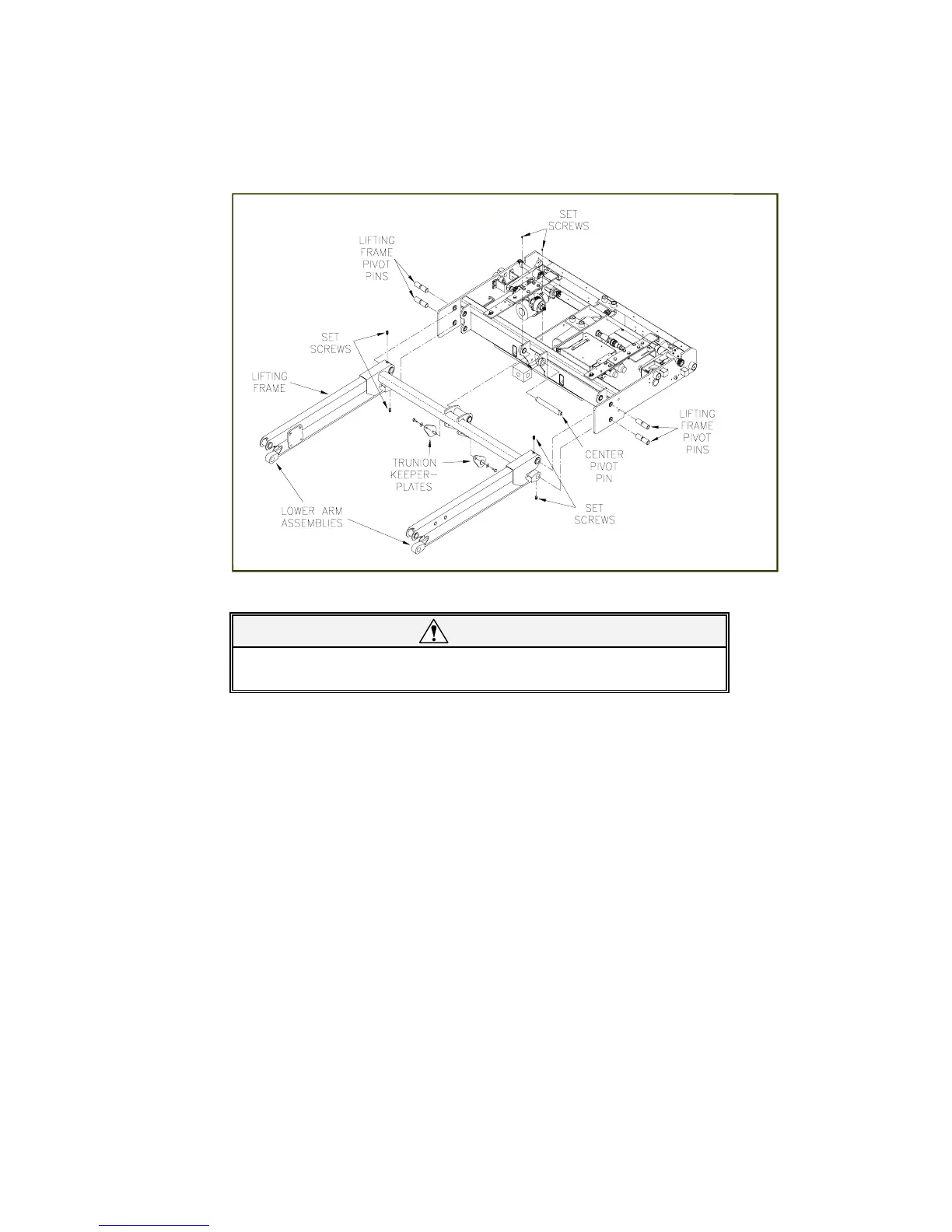
Figure 4-14. Remove four setscrews securing lifting frame pivot pins. Remove two
setscrews securing center pivot pin.
CAUTION!
Do not damage outside surface of pins during removal. A pin should
be replaced if its outer surface is pitted or grooved after removal.
d. Remove two bottom lifting frame pivot pins from carriage with a small punch, and then remove
lower arm assemblies.
e. Remove two trunnion keeper plates.
f. Have an assistant raise lifting frame as high as possible.
g. Remove two upper lifting frame pivot pins and center pivot pin from carriage with a small punch.
h. Pull lifting frame away from carriage.
i.
Lifting Frame Re-installation
Perform re-installation by reversing removal steps, with the following considerations. Verify that
carriage holes and lifting frame holes are properly aligned, and then drive mounting pins in place
using a soft, heavy hammer. Use a thread locker (such as loc-TITE® blue or omniFIT® blue)
when installing new setscrews.
FIGURE 4-14: LIFTING FRAME COMPONENTS
 Loading...