32DF9T02.C
4 - 13
i. Disconnect main electrical harness connector from electronic controller.
j. Position a support stand in front of enclosure to place carriage on.
WARNING!
THE CARRIAGE ASSEMBLY IS HEAVY AND REQUIRES TWO PEOPLE TO REMOVE.
k. Pull carriage out of enclosure, supporting each side, and place on support stand.
NOTE: Care is required while extracting carriage to avoid damage. Watch for possible points of inter-
ference, such as the pins on the release shafts catching on the release reset ramps.
l.
Carriage Re-installation
Perform re-installation by reversing removal steps, with the following considerations. Pull hy-
draulic hose and electrical harness down through service access opening
before inserting car-
riage into enclosure. Route hose and cable back into installed carriage in their original positions.
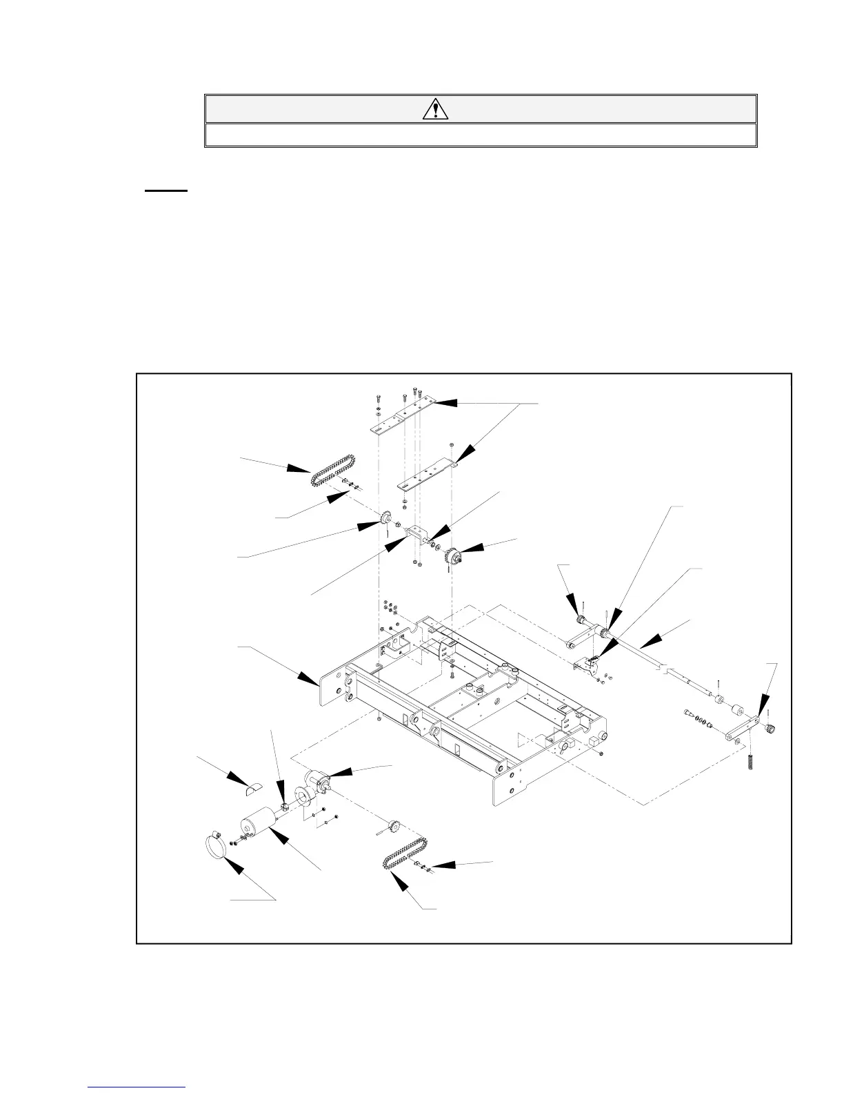
D. DEPLOYMENT SYSTEM
Refer to Figure 4-17. The deployment system propels the traveling frame (carriage, lifting frame, and plat-
form) out of enclosure, or pulls it back in. This section describes major deployment system components, in-
cluding how they operate, how to remove and replace them, and how to perform adjustments.
FIGURE 4-17: DEPLOYMENT SYSTEM COMPONENTS
INTERMEDIATE
SHAFT
TORQUE
LIMITING
CLUTCH
FINAL
DRIVESHAFT
PINION
GEAR
MASTER
LINK
PRIMARY
DRIVE
CHAIN
IN/OUT MOTOR
RUBBER
COUPLER
RUBBER
ISOLATION
GASKET
INTERMEDIATE
SHAFT
SUPPORT
MASTER
LINK
FINAL
DRIVE
CHAIN
GEARBOX
INTERMEDIATE
SHAFT
BRACKETS
MOTOR
RETAINING
CLAMP
SUPPORT
ARM
PLATFORM
RELEASE
SWITCH
CARRIAGE
DRIVESHAFT
SPROCKET
INTERMEDIATE
SHAFT SPROCKET
 Loading...