32DF9T02.C
2 - 7
i. Verify that bridgeplate is resting flat against floor. Adjust right-side rod-end so that shoulder bolt
can be installed without altering bridgeplate position. Install spacer and shoulder bolt, then
tighten rod-end jam-nut.
j. Reconnect positive battery cable at vehicle battery compartment.
k. Remove platform support and operate lift to verify that bridgeplate deploys correctly. Readjust
actuator rod assemblies, if necessary.
4. PLATFORM STOW AND INTERMEDIATE HEIGHT ADJUSTMENTS
The height of platform prior to being pulled into enclosure is referred to as “stow height”. When this
height is properly set, the platform will easily enter enclosure without hanging-up. The stow height is
factory set and normally does not require resetting after lift installation, except when major lift
disassembly is done. However, if the vertical travel limit has been adjusted, then stow height must be
reprogrammed.
Most dedicated entry models have an additional platform position referred to as “intermediate height”.
This height is generally a few inches below floor height, and is also factory-set. The height may be
reprogrammed for specific applications, or after major repair work. Some dedicated entry models move
the platform from the ground directly to floor height, without an intermediate stop.
An optional programming switch kit is available to program the stow and intermediate heights into the
controller memory. It is Ricon part number 17885.
NOTE: The stow and intermediate height values are stored indefinitely in the controller memory. Programming
the controller will clear the present value and store a new value.
a. To Program Stow Height:
1) Deploy platform.
2) Use manual back-up pump in combination with manual pressure release valve to position
top the surface of the platform lifting arms at the same height as the top surface of carriage.
This alignment assures that platform can be pushed into enclosure without difficulty.
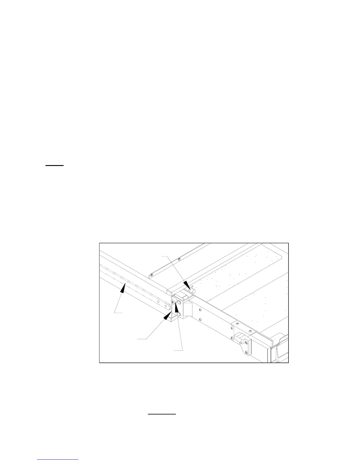
3) Refer to
Figure 2-4. Release manual platform lock, and then hand-push platform into
enclosure. Stop pushing when front face of white stow guide block (tear-drop shaped
plastic block) is adjacent to front edge of enclosure. The stow guide block will be visible
from front of lift.
4) Lower platform by opening manual pressure release valve (located on pump assembly),
and let stow guide blocks (left side and right side) settle on guide rails. Close valve.
5) Raise platform with manual back-up pump so that both left and right side stow guide blocks
are approximately 1/32 inch above guide rails.
6) Hand-pull platform completely
out of enclosure; the platform must lock in place to assure
accurate data entry. Check lock by attempting to push platform into enclosure; it must not
move.
FIGURE 2-4: STOW GUIDE BLOCK ALIGNMENT
GUIDE RAIL
(INSIDE)
STOW
GUIDE BLOCK
RELEASE
MANUAL PLATFORM
ENCLOSURE
 Loading...