32DF9T02.C
4 - 27
5. HYDRAULIC HOSE AND MAIN ELECTRICAL HARNESS
A single flexible conduit, containing both a hydraulic hose and an electrical harness, is routed inside the
enclosure. It is routed between the pull box and carriage. The hydraulic hose is part of a line that con-
nects the hydraulic pump (located in pump box) to the hydraulic cylinder (platform lifting cylinder). The
electrical harness provides power to the lift, and also carries pendant and hydraulic pump motor signals
to the carriage-mounted electronic controller.
a. Hydraulic Hose and Main Electrical Harness Removal
1) Refer to CARRIAGE REMOVAL section and remove platform, lifting frame, and carriage.
2) Refer to
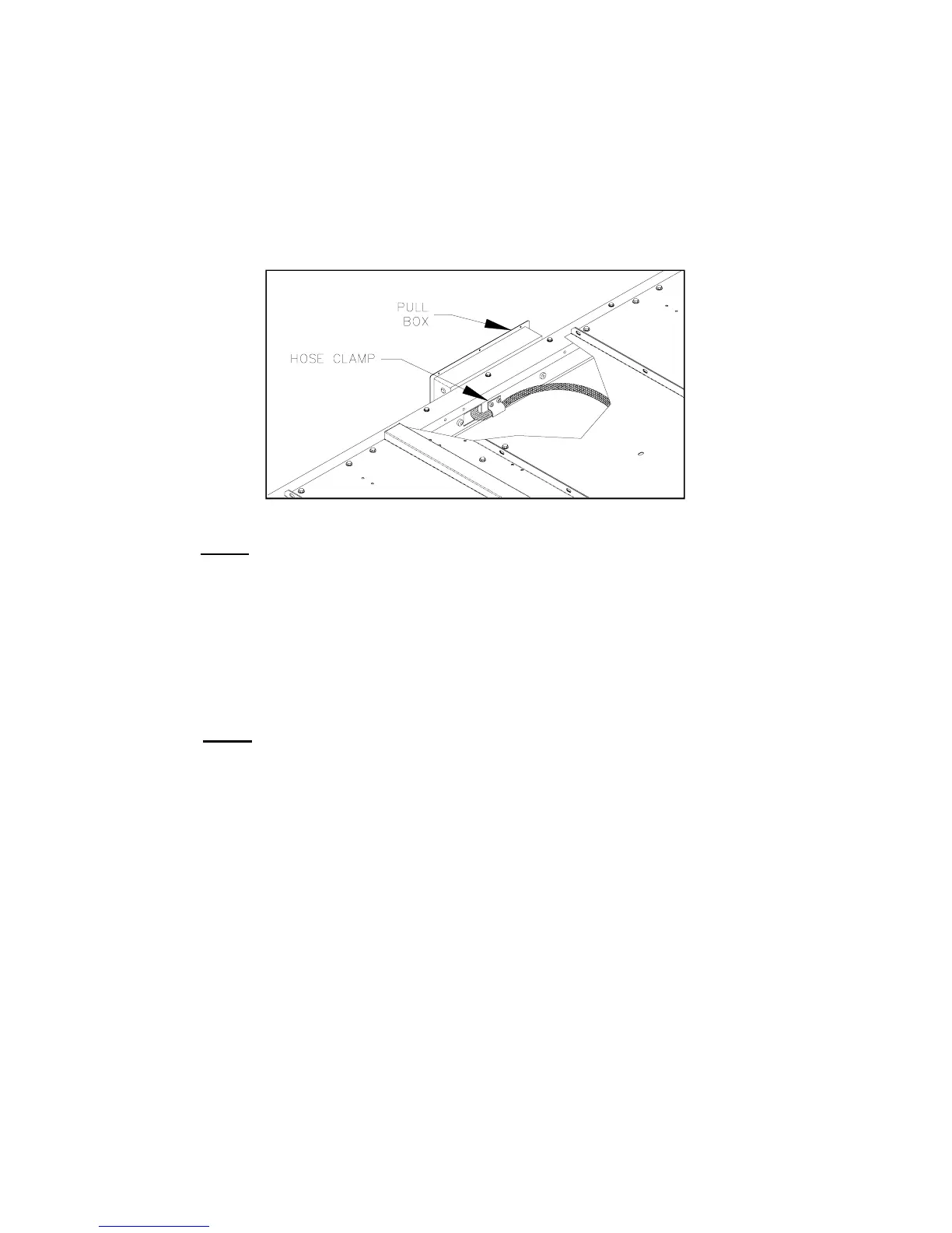
Figures 4-24 and 4-25. Remove hose retaining clamp from bottom of carriage.
Remove hose clamp behind pull box (inside enclosure).
NOTE: The following step will spill hydraulic fluid; have dry rags on hand.
3) Disconnect hydraulic hose from Quick-Disconnect fitting at lifting cylinder. Disconnect main
electrical harness connector from electronic controller (mounted to carriage).
4) Disconnect hydraulic hose from fitting inside pullbox. Disconnect main electrical harness
from terminal strip inside pullbox. Make a note of wire colors and terminal numbers. Also,
note the routing of conduit and how it is secured.
5) Remove main electrical harness and hydraulic hose from enclosure (cut tie wraps, where
necessary).
b. Hydraulic Hose and Main Electrical Harness Installation
NOTE:
This procedure assumes the conduit containing the main electrical harness and hydraulic
hose has been removed.
1) Refer to CARRIAGE REMOVAL section and remove platform, lifting frame, and carriage, if
present.
2) Route main electrical harness and hydraulic hose from enclosure pullbox to carriage.
3) Connect hydraulic hose to fitting inside pullbox. Connect main electrical harness to terminal
strip inside pullbox.
4) Route conduit from pullbox to carriage.
5) Connect hydraulic hose to quick-disconnect fitting at lifting cylinder. Connect main electrical
harness connector to electronic controller (mounted in carriage).
6) Position conduit so that it moves freely with carriage; it must not interfere with carriage
movement. The conduit must lie flat against the bottom enclosure cover, and must not twist
or loop as carriage moves in and out of enclosure. Secure conduit with tie wraps, where
necessary.
7)
Refer to Figures 4-24 and 4-25. Install hose retainer clamp on bottom of carriage. Install
hose clamp behind pull box (inside enclosure).
8) Refer to end of Carriage Removal section for instructions to install carriage.
9) Refer to HYDRAULIC BLEEDING section in
Chapter II and bleed system.
FIGURE 4-25: HOSE CLAMP AT PULL BOX
 Loading...