32DF9T02.B
3 - 6
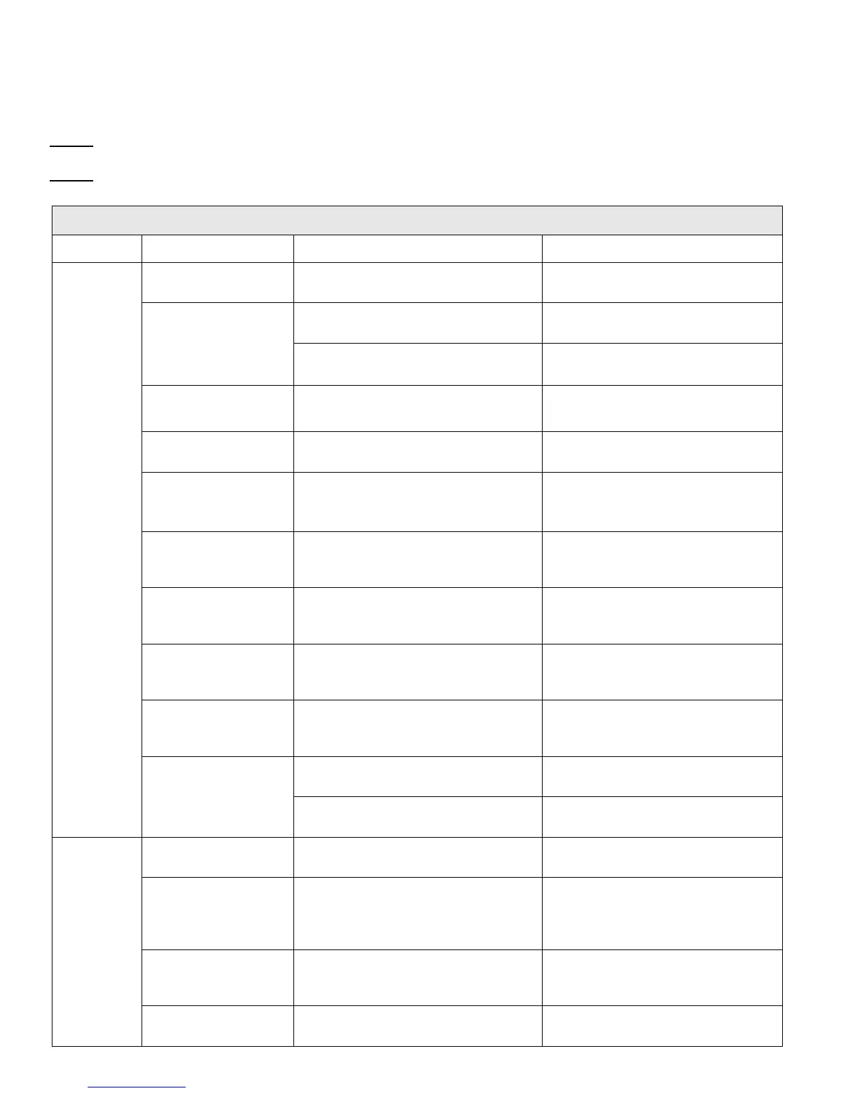
C. TROUBLESHOOTING CHART
Reference is made in the troubleshooting chart to connector pins located on harness connectors and components. Re-
fer to the Wheelchair Lift Electrical Wiring Diagram in Figures 2-11 and 2-12 for identification and location of these com-
ponents and connectors.
NOTE: Figures referenced in the troubleshooting chart are located either in this chapter or other chapters in this man-
ual.
NOTE: Verify that the 24 VDC power supplied to the wheelchair lift by the vehicle is present, and is capable of supply-
ing sufficient electrical current. Also, verify that vehicle interlock requirements are met.
TABLE 3-1: WHEELCHAIR AND STANDEE LIFT TROUBLESHOOTING CHART
SYMPTOM PROBABLE CAUSE TESTS AND CHECKS CORRECTIVE ACTION
24 vdc power is not
available to lift.
Check for 24 vdc at 50 A circuit
breaker.
Switch lift power on.
Check for 24 vdc from pin 7 on TS1 to
30 A circuit breaker (in pump box).
If voltage is not present, replace
power cut-off solenoid.
24 vdc power is not
present in lift.
1. Check for 24 vdc at pin 7 on P2.
2. Check 10A fuse at P2-1.
Replace fuse, if bad.
Lift 50 A circuit breaker
is tripped.
Check for 24 vdc at power cut-off sole-
noid.
Reset breaker.
Lift 30 A circuit breaker
is tripped.
Check for 24 vdc at pin 1 on TS1 (in
pump box).
Reset breaker.
Platform
does not
deploy.
Main harness connec-
tor on controller is
loose.
Check for 24 vdc at pin 1 of P2. Verify secure connection of P2 to
controller.
Carriage-platform
harness connector on
controller is loose.
Check for 24 vdc at pin 2 of P5. Verify secure connection of P5 to
controller.
Obstruction in
enclosure.
Look inside enclosure for foreign ob-
jects and check for twisting of main
harness.
Remove obstruction; check for re-
lated damage.
In/Out motor failure. Check for 24 vdc across In/Out motor
(moves carriage) with “Out” button
pressed.
If voltage is present, replace In/Out
motor.
“In-Out” switch failure
(on control panel).
Verify 24 vdc at pin 6 of P1 with “Out”
button pressed.
If voltage is not present at pin 6, re-
place “In-Out” switch (section F-1 of
chap 4).
Check for 24 vdc at pin 7 of P1. If voltage is not present, replace con-
troller.
Controller failure.
Check for 24 vdc at pin 6 of P2 with
“Deploy” button pressed.
If voltage is present, replace control-
ler.
Platform not fully
deployed.
Check for 24 vdc at pin 5 of P5. Press “Out” button on control panel.
Hydraulic quick-
disconnect hose fitting
to cylinder is not se-
cure.
Verify that quick-disconnect connector
is fully engaged.
If loose, remake connection.
Down valve failure
(part of hydraulic pump
assembly).
Check for 24 vdc at pin 4 of TS1. If voltage is present, replace down
valve (or entire hydraulic pump as-
sembly).
Platform
does not
lower.
Up-Down switch (on
control panel) failure.
Check for 24 vdc at pin 4 of P1. If voltage is not present, replace
switch (section F-1 of chap 4).
 Loading...