32DF9T02.C
4 - 12
6. CARRIAGE REMOVAL
The following procedure describes removal of carriage after platform and lifting frame have been re-
moved.
The carriage, lifting frame, and platform are referred to as a “
travelling frame”, when assembled to-
gether (Refer to
Figure 4-2). The travelling frame can be removed from enclosure as a unit. Be pre-
pared to handle the combined weight of the carriage, lifting frame, and platform when removing and in-
stalling.
Refer to end of this section for re-installation notes.
a. Deploy platform using control pendant (
/OUT).
b. Refer to Platform Removal section and remove platform.
c. Refer to Lifting Frame Removal section and remove lifting frame.
d. Verify that positive battery cable is disconnected. Lower access panel by following Lift Service
Access instructions at beginning of this chapter.
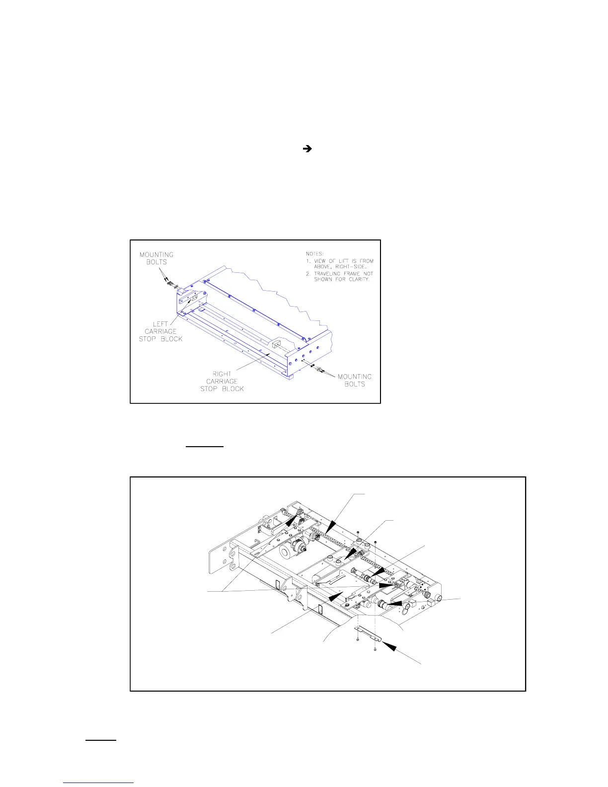
e. Refer to
Figure 4-15. The carriage stop block mounting bolts are accessible from under vehicle,
or from the front of enclosure. Remove bolts and both stop blocks.
f. Refer to
Figure 4-16. Verify that platform release shafts are in the engaged position (rotated in
the direction opposite
to what is indicated on adjacent decal). Deflect final driveshaft downward
to disengage its pinion gears from gear rack. Use nylon tie-wraps, or similar, to hold driveshaft
disengaged.
g. Remove two nuts fastening hose retaining clamp (located at bottom, rear-center of carriage).
NOTE: The following step will spill hydraulic fluid; have dry rags on hand.
h. Disconnect hydraulic hose from quick-disconnect.
FIGURE 4-15: CARRIAGE STOP BLOCK LOCATIONS
FIGURE 4-16: CARRIAGE COMPONENTS
HYDRAULIC
QUICK-DISCONNECT
MAIN
ELECTRICAL
CONNECTOR
HOSE RETAINER
CLAMP
CONTROLLER
TOP VIEW OF CARRIAGE FROM RIGHT SIDE
HYDRAULIC
CYLINDER
FINAL
DRIVESHAFT
MANUAL RELEASE
RESET RAMPS
 Loading...